


 English
 中文简体
 русский
 Español
 عربى

Rated Voltage 3.6/6kV–26/35kV XLPE Insulated Power Cable: Design, Performance, Applications, and Manufacturing Strengths
Content
- 1 Product Overview
- 2 Why XLPE Insulation Is Important
- 3 Key Construction of the Cable
- 4 Available Cable Types
- 5 Electrical and Thermal Performance
- 6 Short-Circuit Capability and Voltage Testing
- 7 Rated Voltage Selection
- 8 Installation Flexibility
- 9 Advantages Compared with Alternative Cable Solutions
- 10 Manufacturing Process and Quality Control
- 11 Manufacturing Strengths of Wuxi Guanghuan Cable Co., Ltd.
- 12 Applications in Power Networks
- 13 Standards and Optional Specifications
- 14 How to Select the Correct Cable
- 15 Installation and Maintenance Recommendations
- 16 Q&A
- 16.1 What voltage range does this XLPE power cable cover?
- 16.2 What is the maximum long-term conductor temperature?
- 16.3 What is the maximum short-circuit conductor temperature?
- 16.4 Can the cable use either copper or aluminum conductors?
- 16.5 What is the difference between YJV and YJLV?
- 16.6 When is armor required?
- 16.7 Can the cable be directly buried?
- 16.8 What is the minimum bending radius?
- 16.9 What partial discharge performance is specified?
- 16.10 What standards are available?
- 16.11 How does the manufacturer support quality assurance?
- 16.12 What information should be provided when requesting a quotation?
- 17 Conclusion
- 18 References
- 19 Product: Rated Voltage 3.6/6kV–26/35kV XLPE Insulated Power Cable
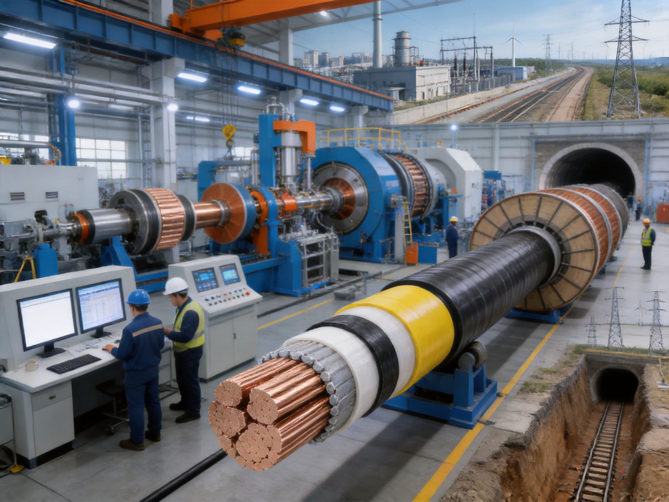
Medium- and high-voltage power distribution systems require cables that can transmit electrical energy safely, continuously, and efficiently under demanding operating conditions. As networks expand into urban areas, industrial parks, infrastructure projects, renewable energy facilities, tunnels, and underground corridors, cable systems must provide more than basic conductivity. They must also offer dependable insulation, controlled electric fields, mechanical protection, resistance to moisture and chemicals, and predictable performance throughout their service life.
The rated voltage 3.6/6kV–26/35kV XLPE insulated power cable is designed for these requirements. It combines a copper or aluminum conductor with cross-linked polyethylene insulation, semiconductive screening layers, a metallic screen, optional armoring, and a protective PVC or PE outer sheath. This construction allows the cable to operate in fixed power transmission and distribution installations where reliability, thermal stability, and installation flexibility are essential.
Manufactured by Wuxi Guanghuan Cable Co., Ltd., the product is part of a broad power cable portfolio that includes electrical equipment wires and cables, bare conductors, overhead insulated cables, rail transit cables, energy storage cables, photovoltaic cables, and wind power cables. The company’s production capabilities, testing facilities, technical personnel, and quality management systems support the consistent manufacture of cables for different voltage levels, conductor materials, core configurations, sheath materials, and installation environments.
Product Overview
The 3.6/6kV–26/35kV XLPE insulated power cable is intended for power-frequency transmission and distribution systems with rated voltages ranging from 3.6/6kV to 26/35kV. It can be manufactured as a single-core or three-core cable, using either copper or aluminum conductors. Depending on the application, the cable may be supplied with a PVC sheath, PE sheath, steel tape armor, or steel wire armor.
The central insulation material is cross-linked polyethylene, commonly abbreviated as XLPE. During production, polyethylene molecules are transformed from a linear thermoplastic structure into a three-dimensional network structure through a controlled chemical or physical cross-linking process. This transformation gives the insulation improved thermal resistance, mechanical strength, aging resistance, and environmental stability compared with conventional thermoplastic insulation.
The cable is suitable for fixed installation in distribution networks, industrial plants, substations, infrastructure projects, tunnels, cable trenches, and direct-buried underground systems. Its relatively simple structure and low weight compared with some alternative high-voltage cable designs can simplify transportation, handling, jointing, and installation planning.
XLPE insulation also permits a maximum long-term conductor operating temperature of 90°C. Under short-circuit conditions lasting no longer than five seconds, the conductor temperature may reach a maximum of 250°C, subject to the applicable design and installation conditions. These thermal characteristics allow the cable to carry substantial electrical loads while maintaining an appropriate safety margin.
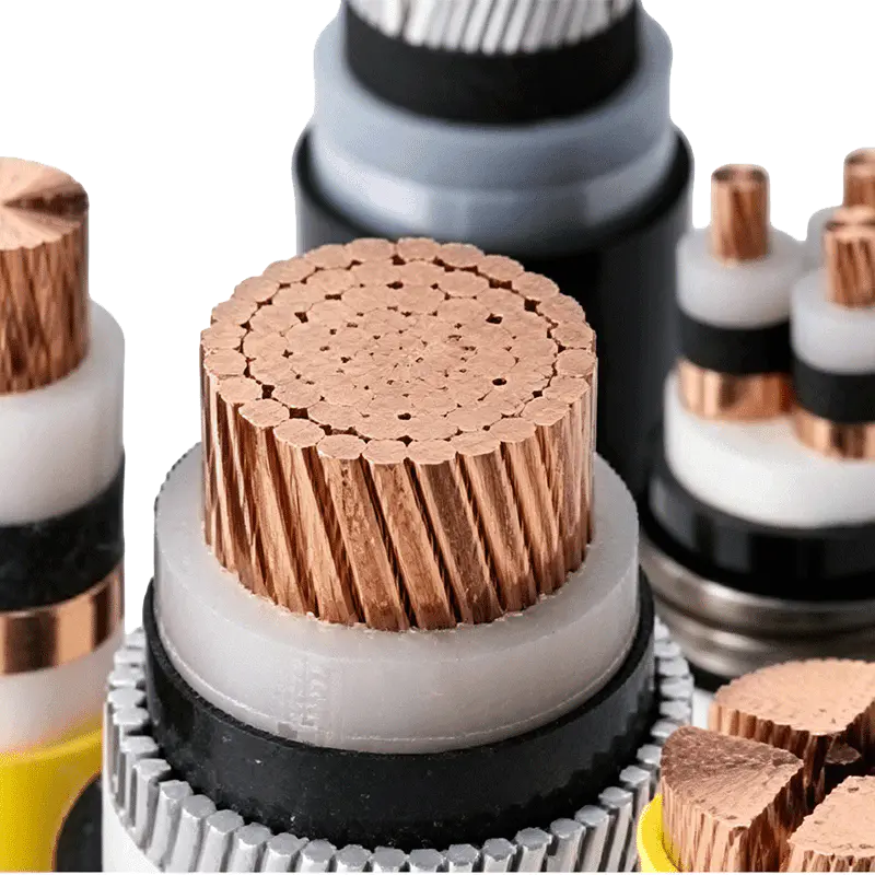
Rated Voltage 3.6/6kV–26/35kV XLPE Insulated Power Cable
Why XLPE Insulation Is Important
Insulation is one of the most important components of a medium- or high-voltage cable. It must withstand continuous electrical stress, transient overvoltages, thermal cycling, moisture exposure, mechanical movement, and the effects of installation. A cable with excellent conductor performance but inadequate insulation cannot provide reliable service.
XLPE is widely used in modern power cables because its molecular structure provides a balance of electrical, thermal, and mechanical properties. The cross-linked structure reduces the tendency of the material to soften under elevated temperature. It also improves resistance to deformation and supports stable operation during load changes.
Compared with older insulation technologies, XLPE offers several practical advantages:
• Higher permissible continuous conductor operating temperature, allowing greater current-carrying capability when installation conditions are suitable.
• Strong electrical insulation performance, supporting reliable operation across the 3.6/6kV–26/35kV voltage range.
• Good resistance to moisture, chemicals, and environmental aging.
• Lower weight and simpler cable construction compared with some oil-filled or pressure-assisted cable systems.
• Easier installation in tunnels, trenches, indoor cable routes, and direct-buried applications.
• Reduced maintenance requirements because the cable does not require a continuous oil supply or pressure-monitoring system.
• Stable performance over repeated heating and cooling cycles when the cable is correctly selected and installed.
The quality of XLPE insulation depends not only on the material itself but also on the cleanliness, extrusion control, concentricity, cross-linking conditions, cooling process, and testing procedures used during manufacturing. For this reason, advanced production equipment and online monitoring are essential in medium- and high-voltage cable production.
Key Construction of the Cable
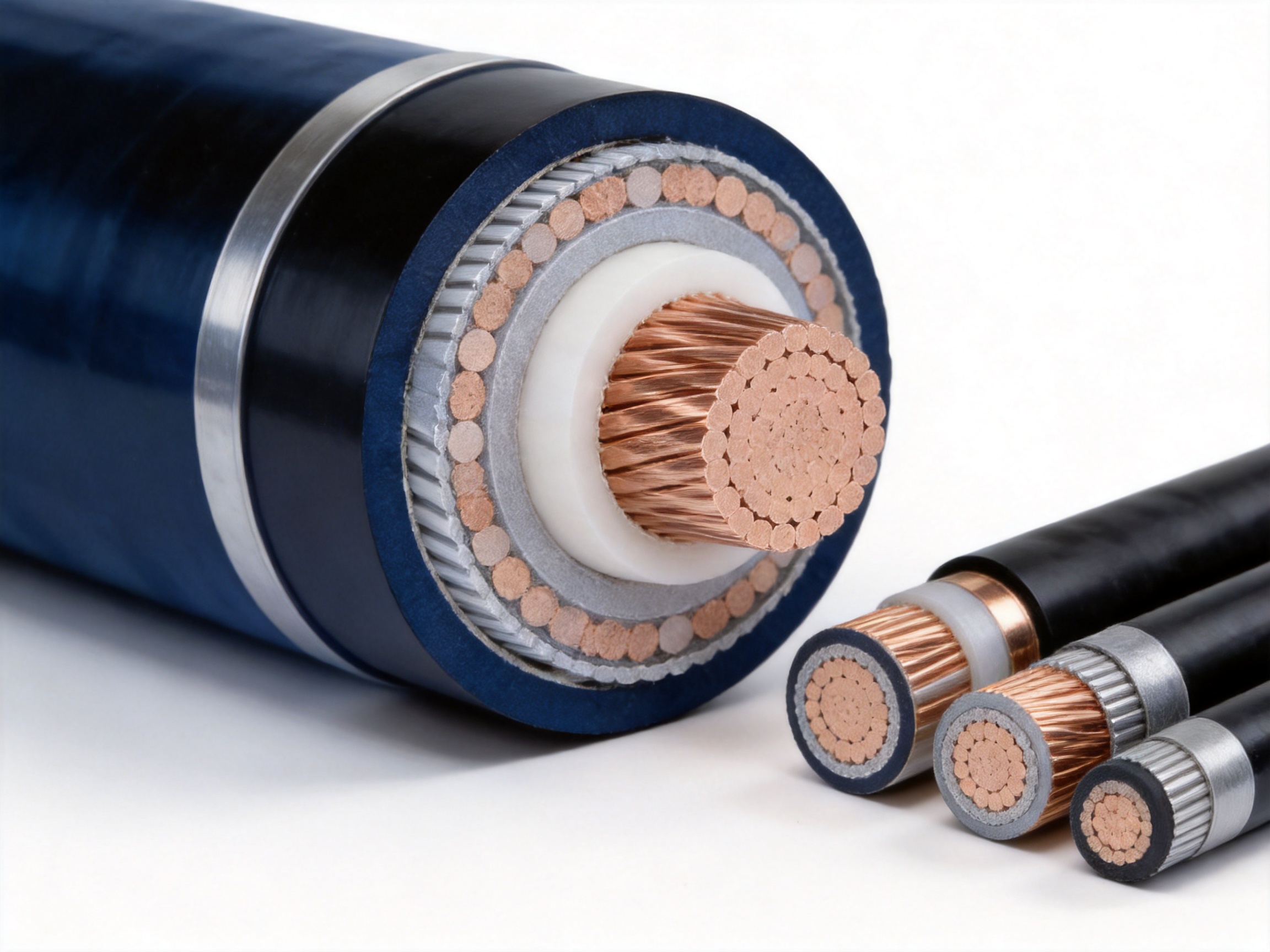
The product is composed of multiple functional layers. Each layer performs a specific electrical, mechanical, or environmental protection role. The complete structure can be adapted according to voltage class, conductor size, installation method, mechanical requirements, and customer specifications.
Conductor
The conductor is manufactured from high-purity copper or aluminum. Copper provides high conductivity, strong mechanical performance, and excellent connection characteristics. Aluminum has a lower density and can reduce overall cable weight, which may be advantageous for long cable routes and projects where transportation or installation weight is an important consideration.
Conductor cross-sectional areas are selected according to the required load current, voltage drop, short-circuit current, installation method, ambient conditions, and permissible temperature rise. Available conductor sizes cover a broad range. Typical copper conductor sizes extend from 25mm² to 1000mm² for single-core designs and from 25mm² to 500mm² for three-core designs. Aluminum conductor sizes generally begin at 50mm², with larger sizes available according to the voltage class and construction.
Conductors are manufactured in accordance with the applicable requirements of GB/T 3956. Proper conductor compaction, stranding, dimensional control, and surface quality are important because irregularities can increase electric field concentration or complicate the extrusion of the semiconductive screen and insulation.
Conductor Screen
The conductor screen is an extruded semiconductive layer applied over the conductor. It smooths the conductor surface and helps distribute electrical stress evenly around the insulation. By reducing localized electric field concentration, the conductor screen supports reliable insulation performance and reduces the risk of partial discharge caused by surface irregularities.
Close contact between the conductor screen and the XLPE insulation is essential. The screen must be uniform, continuous, and free from inclusions or defects. In modern cable production, the conductor screen, insulation, and insulation screen are often applied using carefully controlled extrusion processes to maintain concentricity and cleanliness.
XLPE Insulation
The XLPE insulation layer provides the principal dielectric barrier between the energized conductor and the metallic screen or earth. Its thickness depends on the rated voltage and the applicable product standard. The insulation must maintain uniform thickness around the conductor and remain free from voids, contaminants, moisture, and extrusion imperfections.
The insulation system is designed to withstand power-frequency voltage tests, impulse voltage tests, and partial discharge testing. For the stated voltage range, the cable is subjected to testing procedures appropriate to its rated voltage level. These tests verify that the insulation can withstand normal electrical stress as well as temporary overvoltage and lightning-related surges.
Insulation Screen
The insulation screen is another extruded semiconductive layer applied over the XLPE insulation. It works with the conductor screen and metallic screen to control the electric field within the cable. The insulation screen should be tightly bonded to the insulation while remaining removable or treatable as required for cable accessories and jointing systems.
A stable insulation screen is particularly important in medium- and high-voltage cables because defects at the interface can contribute to electrical treeing, partial discharge, and long-term insulation deterioration. Controlled extrusion and online eccentricity monitoring help maintain the dimensional consistency of this layer.
Metallic Screen
The metallic screen provides an electrical path for capacitive charging current, leakage current, and short-circuit current. Depending on the cable design, it may consist of copper tape, copper wires, or a combination of metallic components.
For cable voltage classes of 21/35kV and 26/35kV, as well as cables with nominal cross-sectional areas above 500mm², a copper wire shielding structure may be adopted. In such cases, the letter “S” may be added to the product model, such as YJSV or YJLSV22. The specific screen design should be selected according to the system earthing method, fault current, fault duration, bonding arrangement, and requirements of the installation design.
Filling and Binding Layers
For three-core cables, non-hygroscopic filling materials are used to maintain the roundness of the cable and support the cores. Binding tape holds the assembly together and provides a stable base for the inner sheath or armor. The use of non-hygroscopic materials helps reduce the possibility of moisture migration within the cable structure.
Inner Sheath
An inner sheath may be included between the insulated cores and the armoring layer. It separates the electrical components from the armor, improves structural stability, and provides an additional protective layer. The exact material and thickness depend on the cable design and applicable standard.
Armoring
Armoring is selected when the cable must withstand external mechanical forces. Steel tape armor offers protection against compression and impact, making it suitable for certain buried or protected installations. Steel wire armor provides improved resistance to tensile forces and may be selected for routes where pulling forces or vertical installation conditions require additional mechanical support.
Outer Sheath
The outer sheath protects the cable against moisture, abrasion, chemical exposure, soil conditions, and general environmental contact. PVC sheaths offer balanced mechanical and environmental performance for many indoor, tunnel, trench, and underground applications. PE sheaths provide strong moisture resistance and can be selected for specific outdoor, buried, or chemically demanding environments.
Available Cable Types
The product range includes unarmored and armored configurations with copper or aluminum conductors. The principal types include the following:
| Type | Construction | Typical application |
| YJV | Copper conductor, XLPE insulation, PVC sheath | Indoor, tunnel, trench, or direct-buried installation without significant external mechanical force |
| YJLV | Aluminum conductor, XLPE insulation, PVC sheath | Fixed power distribution installations where reduced cable weight is beneficial |
| YJY | Copper conductor, XLPE insulation, PE sheath | Applications requiring a PE outer sheath and enhanced moisture resistance |
| YJLY | Aluminum conductor, XLPE insulation, PE sheath | Outdoor or underground power distribution systems requiring an aluminum conductor |
| YJV22 | Copper conductor, XLPE insulation, steel tape armor, PVC sheath | Installations requiring resistance to external compression and mechanical impact |
| YJLV22 | Aluminum conductor, XLPE insulation, steel tape armor, PVC sheath | Armored underground and industrial installations |
| YJV23 | Copper conductor, XLPE insulation, steel tape armor, PE sheath | Buried applications requiring both armor and a PE outer sheath |
| YJLV23 | Aluminum conductor, XLPE insulation, steel tape armor, PE sheath | Underground power systems requiring aluminum conductors and armor |
| YJV32 | Copper conductor, fine steel wire armor, PVC sheath | Installations requiring external mechanical protection and defined pulling strength |
| YJLV32 | Aluminum conductor, fine steel wire armor, PVC sheath | Mechanically demanding installations using aluminum conductors |
| YJV33 | Copper conductor, fine steel wire armor, PE sheath | Installations requiring tensile support and a PE outer sheath |
| YJLV33 | Aluminum conductor, fine steel wire armor, PE sheath | Mechanically demanding underground or vertical applications |
The cable model should not be selected solely by conductor material or rated voltage. The complete installation environment must be considered. The designer should evaluate mechanical loading, water exposure, soil thermal resistivity, fault current, cable spacing, magnetic effects, bend radius, sheath bonding, and local regulations before finalizing the cable specification.
Electrical and Thermal Performance
The long-term maximum permissible conductor temperature is 90°C. This value is one of the principal advantages of XLPE insulation because it permits a higher operating temperature than many conventional thermoplastic insulation systems. However, the allowable current is determined by the complete thermal environment rather than conductor temperature alone.
Current-carrying capacity depends on conductor resistance, insulation losses, metallic screen losses, sheath losses, ambient temperature, soil temperature, soil thermal resistivity, installation depth, cable spacing, ventilation, and the number of circuits installed together. A cable that performs well in open air may require a lower rating when multiple circuits are grouped in a confined trench or installed in soil with high thermal resistivity.
For the standard operating assumptions supplied for the product, the maximum conductor temperature is 90°C, the ambient air temperature is 40°C, the ground temperature is 25°C, soil thermal resistivity is 2.0 K·m/W, installation depth is 0.8m, and the reference arrangement is a single circuit. Single-core cables are installed in parallel with adjacent spacing equivalent to the cable diameter.
Correction factors must be applied when actual conditions differ from these reference conditions. For example, the air-temperature correction factor is 1.18 at 20°C, 1.09 at 30°C, 1.00 at 40°C, and 0.90 at 50°C. This demonstrates that higher ambient temperatures reduce the permissible current, while lower temperatures may increase it.
For soil temperature, the correction factor is 1.08 at 15°C, 1.00 at 25°C, and 0.83 at 45°C. Soil thermal resistivity also has a significant effect. For a single-core cable, the factor is 1.42 at 0.8 K·m/W, 1.00 at 2.0 K·m/W, and 0.75 at 3.5 K·m/W. Higher thermal resistivity makes it more difficult for heat to leave the cable and therefore reduces the allowable current.
Short-Circuit Capability and Voltage Testing
During a short circuit lasting no more than five seconds, the maximum conductor temperature shall not exceed 250°C. The actual short-circuit capability depends on conductor cross-sectional area, conductor material, initial temperature, fault duration, and the protection system. Metallic screen sizing must also be checked because the screen may carry substantial fault current during an earth fault.
Representative maximum conductor short-circuit current values are provided for different conductor sizes. For example, a 25mm² copper conductor has a listed maximum short-circuit current of approximately 3.58kA, while a 630mm² copper conductor has a listed value of approximately 90.14kA under the stated reference conditions. Aluminum values are lower for the same nominal cross-sectional area because of differences in electrical and thermal properties.
The cable is tested using multiple methods. A five-minute power-frequency AC voltage test verifies the basic insulation withstand capability. A four-hour AC voltage test provides an extended withstand assessment. Impulse voltage testing verifies resistance to transient overvoltages associated with lightning or switching events. Partial discharge testing evaluates the quality of the insulation system and interfaces.
At 1.73U0, the maximum partial discharge level is specified as no more than 5pC. Low partial discharge performance is important because repeated localized discharges can gradually damage insulation and create electrical trees. A low measured discharge level indicates effective control of material cleanliness, insulation extrusion, screen interfaces, and manufacturing conditions.
For the 3.6/6kV through 26/35kV range, the specified impulse voltage test values extend from 60kV to 250kV, depending on the rated voltage. These tests provide a meaningful verification of the cable’s ability to withstand short-duration electrical stress beyond normal operating voltage.
Rated Voltage Selection
Cable rated voltage is expressed using the format U0/U(Um). Each value has a specific meaning and must correspond to the electrical system in which the cable will operate.
U0 is the rated power-frequency voltage between the conductor and earth or metallic screen for which the cable is designed. U is the rated power-frequency voltage between conductors. Um is the maximum value of the highest system voltage that the equipment can withstand.
The cable voltage class must be selected according to the system configuration, neutral treatment, earth-fault duration, switching conditions, and insulation coordination. The first class is suitable for systems where a single-phase earth fault is cleared quickly. Under the stated conditions, the earth-fault duration does not exceed one minute for each fault and does not exceed eight hours in total, with a cumulative annual duration not exceeding 125 hours.
The second class is intended for systems with more frequent or longer earth faults and requires a higher level of insulation performance. The selection between the first and second class should be made by the electrical system designer based on the actual network earthing arrangement and protection characteristics.
| System voltage U (kV) | Maximum system voltage Um (kV) | U0, first class (kV) | U0, second class (kV) |
| 1 | 1.2 | 0.6 | 0.6 |
| 3 | 3.6 | 1.8 | 3.6 |
| 6 | 7.2 | 3.6 | 6 |
| 10 | 12 | 6 | 8.7 |
| 15 | 17.5 | 8.7 | 12 |
| 20 | 24 | 12 | 18 |
| 35 | 42 | 21 | 26 |
Correct voltage selection improves system safety and prevents the use of an insulation level that is unsuitable for the network. The cable manufacturer can provide technical assistance when customers need to confirm voltage class, conductor size, metallic screen arrangement, armor type, or sheath material.
Installation Flexibility
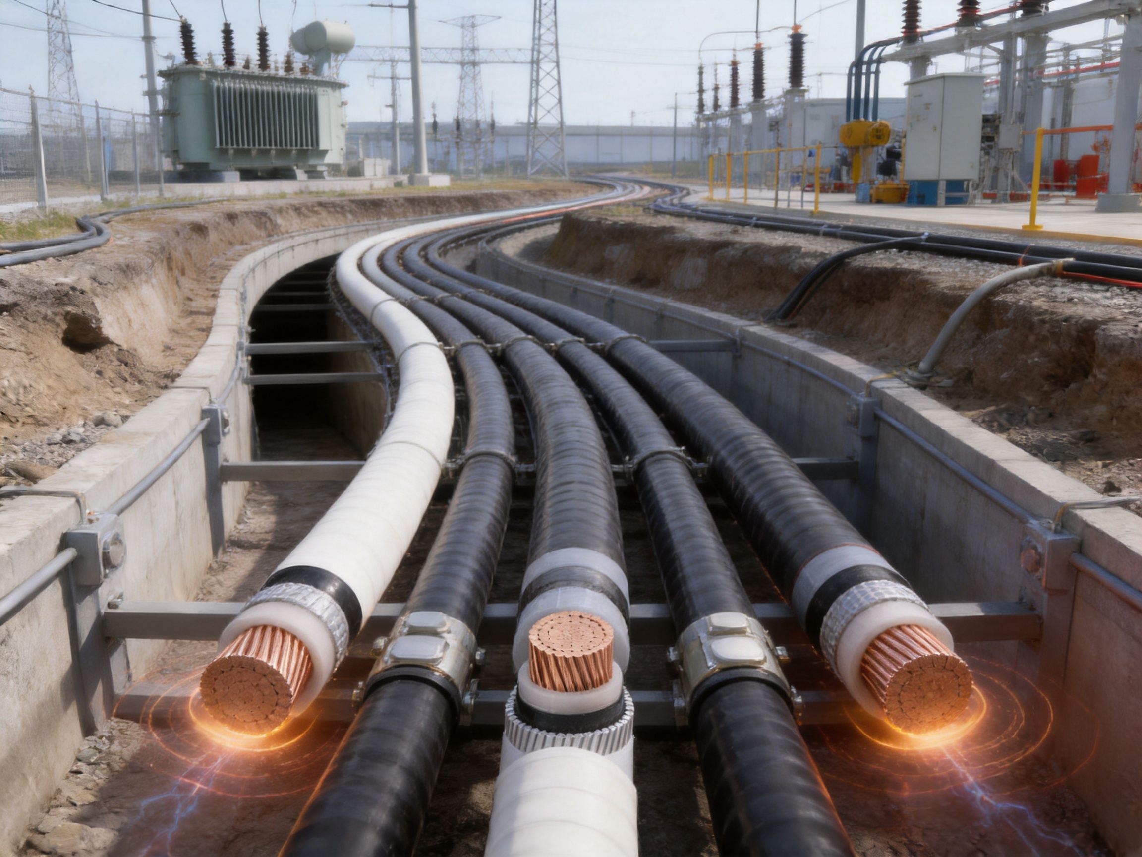
The cable can be installed indoors, in tunnels, in cable trenches, or directly buried underground. Unarmored cables are suitable where the installation route provides sufficient mechanical protection. Armored cables should be considered where the cable may be exposed to compression, impact, pulling tension, or other external mechanical forces.
The minimum bending radius is an important installation requirement. For three-core cables, the bending radius should not be less than 15 times the cable outer diameter. For single-core cables, the minimum bending radius should not be less than 20 times the cable outer diameter. Temporary bending during drum handling and permanent bending during installation should both be controlled.
The ambient temperature during installation should not be lower than 0°C. At lower temperatures, sheath and insulation materials may become less flexible, increasing the risk of surface damage or excessive mechanical stress. If installation must be carried out in cold conditions, appropriate cable-warming and handling procedures should be considered.
When single-core AC cables are installed, magnetic effects must be evaluated. Ferromagnetic ducts or arrangements that cause excessive circulating currents should be avoided unless the system has been specifically engineered for them. The cable arrangement, spacing, bonding method, and support materials should be designed to minimize losses and prevent overheating.
For direct burial, the designer should confirm the soil thermal resistivity, moisture conditions, installation depth, cable spacing, protection against excavation damage, and requirements for warning tapes or protective tiles. For tunnels and trenches, ventilation, drainage, cable support, fire safety, and access for inspection should be considered.
Advantages Compared with Alternative Cable Solutions
The product offers several advantages compared with less advanced or less suitably configured cable systems. The most important advantage is the combination of XLPE insulation with a multilayer screened construction. This provides electrical stability, good thermal performance, and a practical structure for modern distribution networks.
Compared with conventional thermoplastic insulated cables, XLPE cables can operate at a higher conductor temperature, which may permit a higher current rating under comparable installation conditions. The cross-linked insulation also offers improved dimensional stability and resistance to thermal deformation.
Compared with oil-filled or pressure-assisted cable systems, XLPE cables generally have a simpler installation and maintenance profile. They do not require a continuous oil circulation system, pressure monitoring, or the same degree of auxiliary equipment. This can simplify project planning and reduce the number of maintenance points over the operating life of the network.
Compared with unarmored cables in mechanically exposed locations, armored versions provide an additional barrier against compression, impact, and pulling stress. Steel tape armor and steel wire armor can be selected according to the dominant mechanical risk rather than applying one construction to every project.
Compared with using one conductor material for all applications, the availability of copper and aluminum options allows a more balanced project decision. Copper may be selected when compact dimensions, high conductivity, or connection performance are priorities. Aluminum may be advantageous when cable weight and material cost are significant design considerations.
The broad range of voltage classes and conductor sizes also reduces the need to adapt a project around a limited product range. Customers can select a cable closer to the actual load, system voltage, installation route, and fault-level requirements.
Manufacturing Process and Quality Control
Reliable medium- and high-voltage cable production begins with controlled raw material selection. Conductive materials, XLPE compounds, semiconductive compounds, metallic screen materials, armor components, and sheath compounds must meet defined technical requirements before entering production. Material identification, storage conditions, batch control, and inspection records support consistent product quality.
The conductor is first drawn, stranded, and compacted according to the required cross-sectional area and cable design. Dimensional accuracy and surface quality are checked to ensure that the conductor can receive a uniform semiconductive screen. The conductor resistance is verified against the relevant standard, including the requirements of GB/T 3956.
The conductor screen, XLPE insulation, and insulation screen are applied through precision extrusion. For high-voltage cables, the cleanliness of the extrusion environment and the stability of the extrusion process are especially important. Contamination, moisture, dimensional variation, or eccentricity can compromise partial discharge performance and long-term electrical reliability.
Online eccentricity monitoring is used to observe the position and thickness of the insulation system during production. This allows the manufacturing team to detect deviations early and correct process parameters before a large amount of material is produced. Stable temperature control, extrusion pressure, line speed, and cooling conditions help achieve a concentric and uniform insulation system.
After the insulation system is completed, the metallic screen is applied. Depending on the cable type, this may involve copper tape, copper wires, or a specially designed copper wire shield. For armored cables, the inner sheath, steel tape, or steel wire armor is then applied using controlled tension and overlap. Finally, the PVC or PE outer sheath is extruded and inspected.
Testing is performed throughout the production process and after completion. Electrical resistance, dimensional characteristics, insulation quality, AC withstand voltage, impulse withstand voltage, partial discharge, and appearance are among the characteristics that may be evaluated. High-voltage series resonance testers and partial discharge detectors support the verification of finished cable performance.
Manufacturing Strengths of Wuxi Guanghuan Cable Co., Ltd.
Wuxi Guanghuan Cable Co., Ltd. was founded in 1998 and is headquartered in Guanlin Town, Yixing City, Jiangsu Province, a location recognized as an important cable manufacturing center in China. The company covers more than 100,000 square meters, including more than 45,000 square meters of building area. Its production and testing infrastructure includes more than 70 advanced lines.
The company employs more than 140 people, including more than 30 technical professionals. This combination of production personnel and technical staff supports product development, process optimization, quality management, testing, and customer service. The company reports annual sales revenue of approximately RMB 2 billion and annual output value exceeding RMB 3 billion.
Its product portfolio covers power cables, electrical equipment wires and cables, bare conductors, overhead insulated cables, high-speed railway and urban rail transit cables, energy storage cables, photovoltaic cables, and wind power cables. More than 100 product categories and over 30,000 specifications are offered under the registered Liguang brand.
This broad product scope is relevant to XLPE power cable customers because it demonstrates experience across different conductor technologies, insulation systems, voltage levels, mechanical constructions, and application environments. It also supports coordinated procurement when a project requires several types of cable rather than one isolated product.
The company has obtained ISO 9001 quality management certification, ISO 14001 environmental management certification, ISO 45001 occupational health and safety certification, and ISO 50001 energy management certification. It also holds certifications related to intellectual property, green management, social responsibility, and after-sales service.
Product-related credentials include CCC, TÜV, product carbon footprint, and China Energy-Saving and Environmentally Friendly Product certifications. The company has also passed qualification and capability verification for power cables and conductors conducted by the State Grid Corporation of China. These certifications and verifications do not replace project-specific technical evaluation, but they provide evidence of an established management and production framework.
Advanced equipment such as online eccentricity monitors, high-voltage series resonance testers, and partial discharge detectors is used to support production quality. These instruments are particularly important for medium- and high-voltage cables because the performance of the insulation system cannot be assessed adequately through visual inspection alone.
Applications in Power Networks
In urban distribution networks, the cable can be used for feeder circuits, substation connections, underground distribution corridors, and power supply routes serving commercial or residential districts. Underground installation reduces visual impact and can be useful where overhead corridors are unavailable or undesirable.
In industrial installations, the cable can connect substations, transformers, motor control centers, production facilities, and process equipment. The selection of armor, sheath, conductor material, and screen arrangement should reflect the presence of chemicals, vibration, heat, mechanical traffic, and fault-current requirements.
In infrastructure projects, XLPE power cables can be installed in tunnels, cable trenches, transport facilities, water treatment plants, ports, and large public buildings. The relatively simple construction and range of sheath and armor options allow the cable to be adapted to different routes.
For direct-buried systems, the cable’s outer sheath and optional armor provide protection against moisture and mechanical contact. However, the design must still consider future excavation, ground movement, drainage, soil thermal resistivity, and protection at road or rail crossings.
The product can also support power distribution associated with energy, renewable power, and industrial expansion projects. When used near photovoltaic, wind, or energy storage facilities, the cable must be coordinated with the output voltage, inverter or transformer arrangement, fault level, harmonic environment, installation configuration, and applicable project standards.
Standards and Optional Specifications
The product is manufactured in accordance with GB/T 12706, which covers power cables with extruded insulation and their accessories for rated voltages from 1kV to 35kV. Part 2 addresses cables for rated voltages from 6kV to 30kV, while Part 3 addresses cables for rated voltage 35kV.
Depending on customer requirements and project location, production may also follow IEC standards, British Standards, German Standards, or American Standards. When an international standard is requested, the cable design, testing program, marking, documentation, and acceptance criteria should be confirmed before production.
Standards selection is important because the same general cable designation may have different dimensional, testing, fire, sheath, conductor, or screening requirements under different standards. A complete technical specification should identify the applicable standard, voltage, conductor material, conductor class, core number, screen design, armor, sheath, installation method, and inspection requirements.
How to Select the Correct Cable
The first step is to identify the system voltage and earthing conditions. The selected U0/U(Um) value must match the network’s maximum operating voltage and earth-fault characteristics. A cable with an unsuitable voltage class can compromise insulation coordination even if its conductor size is adequate.
The second step is to calculate the continuous load current. This calculation must include the expected load profile, ambient conditions, installation arrangement, grouping, soil thermal resistivity, and future expansion. Correction factors should be applied rather than relying only on a basic catalog current rating.
The third step is to verify voltage drop and conductor resistance. Long cable routes may require a larger conductor to maintain acceptable voltage at the receiving end. Copper and aluminum alternatives should be compared using total installed cost, weight, connection requirements, losses, and project life-cycle considerations.
The fourth step is to calculate short-circuit thermal withstand. The conductor and metallic screen must both be capable of carrying the prospective fault current for the clearing time specified by the protection system. If the fault duration or current is high, a larger conductor or screen may be required.
The fifth step is to evaluate mechanical and environmental conditions. Direct burial, tunnel installation, vertical routes, cable trays, industrial floors, and exposed outdoor routes impose different requirements. Armor, sheath material, water resistance, tensile strength, and impact protection should be selected accordingly.
The final step is to confirm installation accessories. Terminations, joints, bonding leads, grounding connections, clamps, cleats, glands, and protective systems must be compatible with the cable diameter, insulation screen, metallic screen, and voltage class.
Installation and Maintenance Recommendations
Cable drums should be inspected before handling to confirm that the outer sheath and end seals are intact. The cable should be stored on a firm surface, protected from standing water, and positioned so that the drum cannot roll unexpectedly. During transportation, the drum should remain in the correct rolling direction marked by the manufacturer.
Pulling tension should be controlled according to the conductor material, cable construction, armor type, and manufacturer’s recommendations. Excessive tension can stretch the conductor, deform the insulation system, or damage the sheath. Sidewall pressure should also be controlled when the cable passes through bends.
Rollers, guides, and approved pulling equipment should be used to maintain the minimum bending radius. Sharp edges, dragging over rough ground, and uncontrolled cable drops should be avoided. After installation, the cable should be supported at suitable intervals to prevent sagging and mechanical stress at terminations.
Metallic screens and armor must be bonded and grounded according to the system design. Single-core AC cable bonding requires particular attention because induced voltages and circulating currents can produce additional losses or hazardous touch voltages if the arrangement is not correctly engineered.
After installation, acceptance testing should be performed in accordance with the applicable standard and project requirements. Test records should be retained together with cable drum numbers, route information, joint locations, termination details, and installation dates. Periodic inspection should check exposed sheaths, supports, terminations, grounding connections, and signs of overheating or mechanical damage.
Q&A
What voltage range does this XLPE power cable cover?
The product covers power-frequency rated voltages from 3.6/6kV to 26/35kV. Specific voltage classes include 3.6/6kV, 6/6kV, 6/10kV, 8.7/10kV, 8.7/15kV, 12/20kV, 18/20kV, 18/30kV, 21/35kV, and 26/35kV, subject to the selected standard and construction.
What is the maximum long-term conductor temperature?
The maximum permissible long-term operating temperature of the conductor is 90°C. The actual current-carrying capacity must be corrected for ambient temperature, soil conditions, installation method, cable spacing, and grouping.
What is the maximum short-circuit conductor temperature?
During a short circuit with a maximum duration of five seconds, the conductor temperature should not exceed 250°C. The complete fault-current calculation must also consider the metallic screen and the protection clearing time.
Can the cable use either copper or aluminum conductors?
Yes. The product is available with copper or aluminum conductors. Copper offers high conductivity and strong connection performance, while aluminum can reduce cable weight and may provide economic advantages for suitable installations.
What is the difference between YJV and YJLV?
YJV uses a copper conductor, XLPE insulation, and PVC sheath. YJLV uses an aluminum conductor with XLPE insulation and PVC sheath. The appropriate choice depends on current requirements, cable weight, connection design, project cost, and installation conditions.
When is armor required?
Armor should be considered where the cable may experience external mechanical forces such as compression, impact, pulling tension, or certain vertical loads. Steel tape armor is commonly associated with compression protection, while steel wire armor can provide improved tensile resistance.
Can the cable be directly buried?
Yes. Suitable cable types can be installed directly in the ground, provided that the sheath, armor, thermal design, burial depth, soil conditions, mechanical protection, and route requirements are properly evaluated.
What is the minimum bending radius?
The minimum bending radius is generally not less than 15 times the outer diameter for three-core cables and 20 times the outer diameter for single-core cables. The manufacturer’s project-specific instructions should be followed if they specify a larger value.
What partial discharge performance is specified?
At 1.73U0, the maximum partial discharge is specified as no more than 5pC. Partial discharge testing helps verify the quality and integrity of the cable insulation system.
What standards are available?
The product is manufactured according to GB/T 12706. Depending on the customer’s requirements, production may also follow IEC, BS, DIN, or ASTM-related specifications where applicable to the requested cable design and project.
How does the manufacturer support quality assurance?
Quality assurance is supported through controlled raw materials, precision extrusion, online eccentricity monitoring, high-voltage testing, partial discharge testing, dimensional inspection, and management systems including ISO 9001. The company also maintains certifications and verification related to environmental management, occupational safety, energy management, product conformity, and technical capability.
What information should be provided when requesting a quotation?
Customers should provide system voltage, conductor material, number of cores, conductor cross-sectional area, installation method, cable route length, ambient or soil conditions, short-circuit current, fault duration, armor requirement, sheath preference, applicable standard, delivery location, and any required inspection or certification documents.
Conclusion
The 3.6/6kV–26/35kV XLPE insulated power cable is a versatile solution for modern medium- and high-voltage power transmission and distribution. Its XLPE insulation provides a high permissible operating temperature, reliable dielectric performance, and strong resistance to thermal and environmental stress. The screened multilayer construction supports electric field control, partial discharge performance, and short-circuit protection.
A broad range of conductor materials, conductor sizes, cores, sheaths, screens, and armor constructions allows the cable to be adapted to urban networks, industrial plants, tunnels, cable trenches, direct-buried systems, and major infrastructure projects. Correct cable selection remains essential, particularly with regard to voltage class, current rating, fault current, thermal environment, bonding method, and mechanical protection.
Wuxi Guanghuan Cable Co., Ltd. combines long-term cable manufacturing experience with a large production base, extensive testing capability, technical personnel, multiple management certifications, and a wide product portfolio. Its use of online eccentricity monitoring, high-voltage series resonance testing, and partial discharge detection supports the quality requirements associated with medium- and high-voltage XLPE cable production.
For customers seeking a dependable power cable solution, the product provides a practical balance of electrical performance, installation flexibility, mechanical protection, manufacturing control, and application adaptability. A project-specific technical review with the manufacturer can ensure that the final cable construction meets the network design, installation environment, applicable standard, and long-term operating objectives.
References
GB/T 12706, Power Cables with Extruded Insulation and Their Accessories for Rated Voltages from 1kV to 35kV.
GB/T 3956, Conductors of Insulated Cables.
International Electrotechnical Commission, Power Cables with Extruded Insulation and Their Accessories.
International Electrotechnical Commission, Electric Cables—Calculation of the Current Rating.
Relevant British, German, and American cable standards as specified by individual project requirements.
Manufacturer technical documentation for 3.6/6kV–26/35kV XLPE insulated power cables.
Product: Rated Voltage 3.6/6kV–26/35kV XLPE Insulated Power Cable

-
Rated Voltage 3.6/6kV–26/35kV XLPE Insulated Power Cable
-
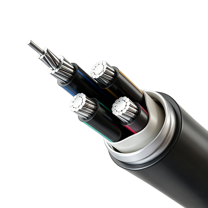
Aluminum Alloy Conductor Plastic Insulated Power Cable (Rated Voltage up to 26/35kV)
-
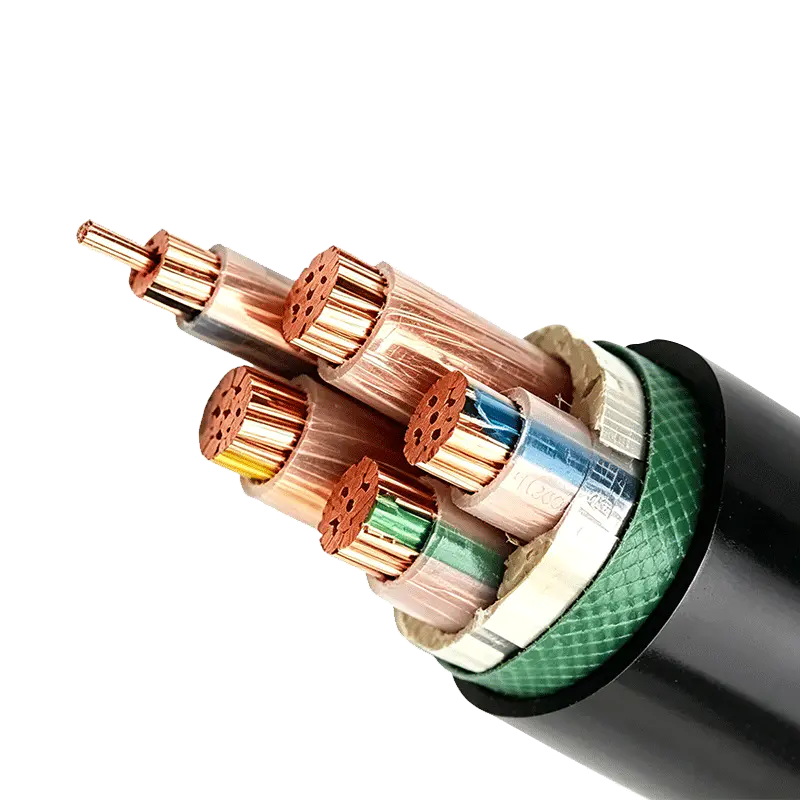
Rated Voltage 0.6/1kV XLPE Insulated Power Cable
-
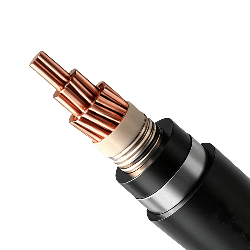
Power Cable for Subway and Urban Rail Transit (Rated Voltage 35kV)
-
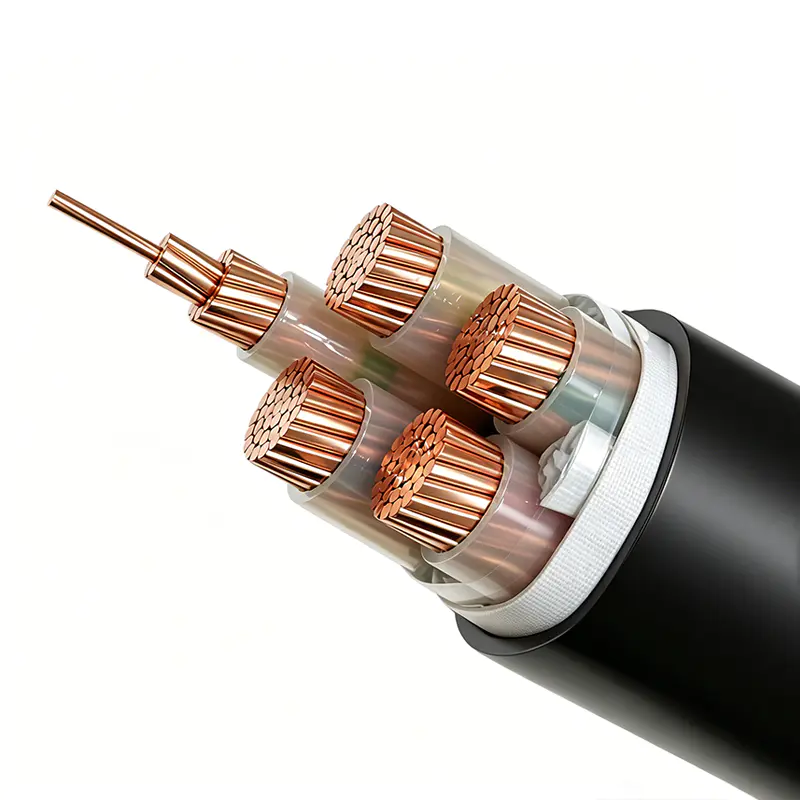
Rated Voltage 1.8/3kV XLPE Insulated Power Cable

Copyright © Wuxi Guanghuan Cable Co., Ltd. All Rights Reserved. Power Cables Manufacturer Electrical Wire And Cable Factory

