


 English
 中文简体
 русский
 Español
 عربى

3.6/6kV–26/35kV XLPE Insulated Power Cable: Design, Performance, Applications, and Manufacturing Excellence
Content
- 1 1. Product Overview
- 2 2. Why XLPE Insulation Is Used for Medium- and High-Voltage Cables
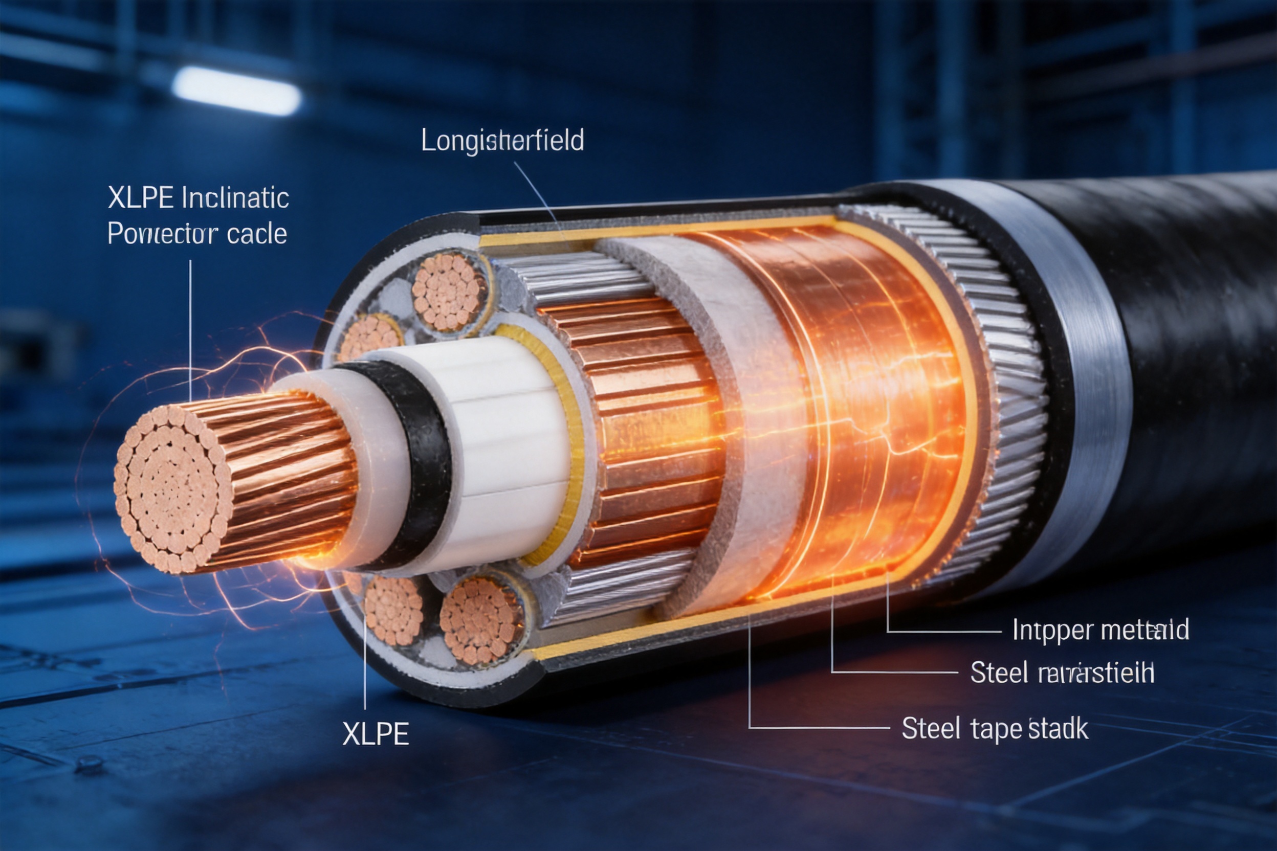
- 3 3. Cable Construction and Function of Each Layer
- 4 4. Voltage Classes and System Selection
- 5 5. Standard Cable Types and Applications
- 6 6. Manufacturing Process for High-Voltage XLPE Cable
- 7 7. Testing and Technical Verification
- 8 8. Current-Carrying Capacity and Installation Correction
- 9 9. Installation Requirements and Best Practices
- 10 10. Advantages Over Competing Cable Technologies
- 11 11. Manufacturing Strengths of Wuxi Guanghuan Cable Co., Ltd.
- 12 12. Typical Applications
- 13 13. Product Selection Checklist
- 14 14. Frequently Asked Questions
- 14.1 Q1: What does 3.6/6kV–26/35kV mean?
- 14.2 Q2: What is the maximum continuous conductor temperature?
- 14.3 Q3: What is the maximum short-circuit conductor temperature?
- 14.4 Q4: Why is XLPE preferred for medium-voltage power cables?
- 14.5 Q5: Should I choose copper or aluminum conductor?
- 14.6 Q6: When is armored cable necessary?
- 14.7 Q7: Can these cables be directly buried?
- 14.8 Q8: What is the purpose of the metallic screen?
- 14.9 Q9: What is partial discharge, and why is it tested?
- 14.10 Q10: What standards can be followed?
- 14.11 Q11: How should cable ampacity be calculated?
- 14.12 Q12: What information should be provided for a quotation?
- 15 15. Conclusion
- 16 References
- 17 Product: Rated Voltage 3.6/6kV–26/35kV XLPE Insulated Power Cable
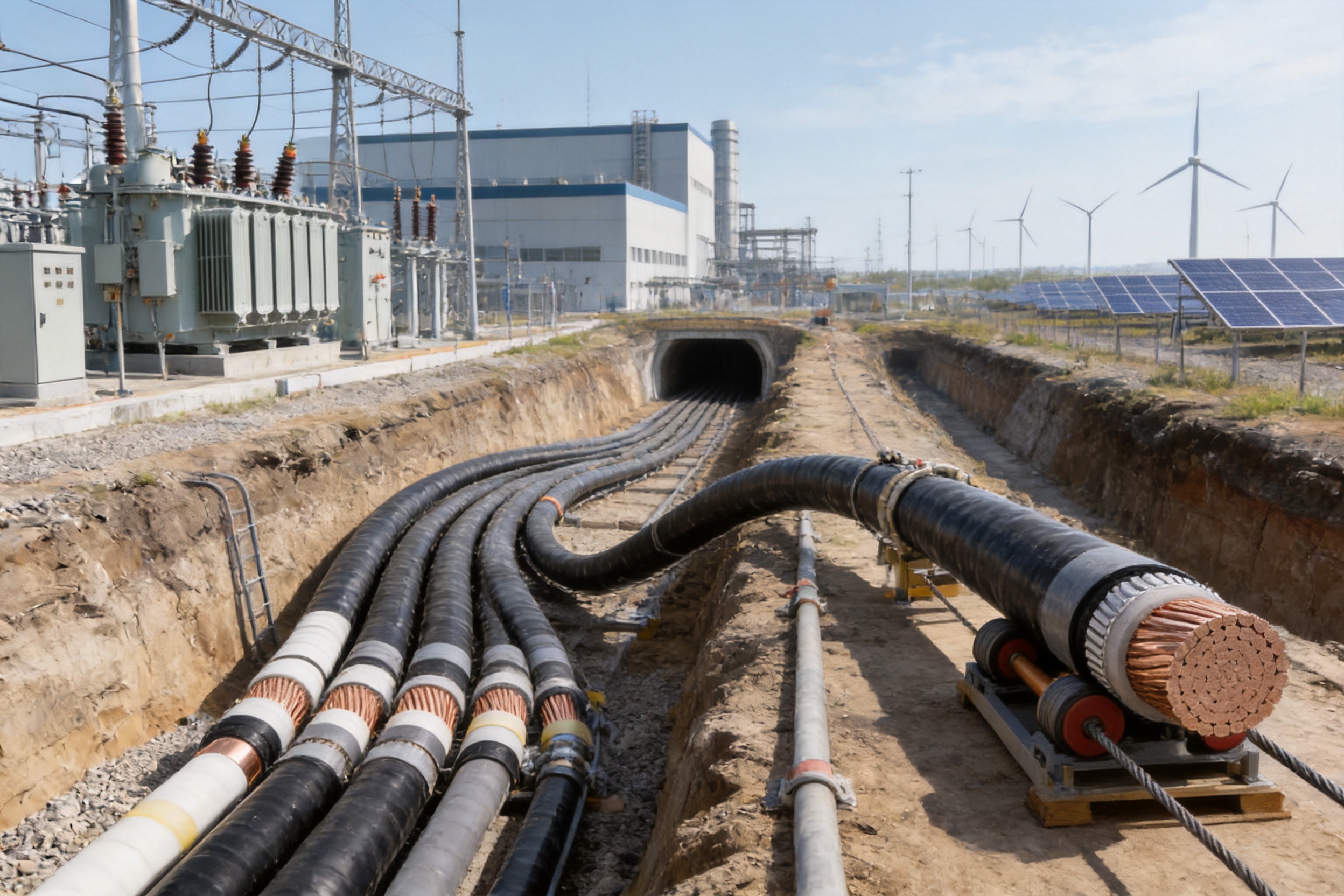
Medium- and high-voltage power distribution systems require cables that can transmit electricity safely, efficiently, and reliably under demanding electrical, thermal, mechanical, and environmental conditions. Rated voltage 3.6/6kV–26/35kV XLPE insulated power cables are engineered for this purpose. They are used in urban distribution networks, industrial facilities, substations, infrastructure projects, tunnels, cable trenches, and direct-burial installations where dependable long-term service is essential.
Compared with older thermoplastic-insulated cable technologies, cross-linked polyethylene, commonly known as XLPE, provides a valuable combination of electrical insulation performance, heat resistance, mechanical stability, chemical resistance, and installation flexibility. The cable can operate continuously with a conductor temperature of up to 90°C, withstand a conductor temperature of up to 250°C during a short circuit of no more than five seconds, and maintain reliable insulation performance over an extended service life when correctly selected and installed.
This article explains the structure, operating characteristics, voltage selection, cable types, manufacturing process, testing requirements, application advantages, and selection considerations for XLPE insulated power cables covering rated voltages from 3.6/6kV to 26/35kV. It also examines how Wuxi Guanghuan Cable Co., Ltd. applies advanced production equipment, quality management systems, technical expertise, and customized manufacturing capabilities to serve demanding power transmission and distribution projects.
1. Product Overview
A 3.6/6kV–26/35kV XLPE insulated power cable is a fixed-installation cable designed for power-frequency transmission and distribution systems. The notation U0/U identifies the rated voltage between the conductor and earth or metallic screen and the rated voltage between conductors. Depending on the system arrangement and grounding method, available cable voltage classes include 3.6/6kV, 6/6kV, 6/10kV, 8.7/10kV, 8.7/15kV, 12/20kV, 18/20kV, 18/30kV, 21/35kV, and 26/35kV.
The cable is available with copper or aluminum conductors. It may be manufactured as a single-core or three-core cable and can be supplied with an unarmored or armored construction. PVC and PE outer sheaths are available to suit different installation environments and mechanical or environmental requirements.
Typical installations include indoor cable systems, underground tunnels, cable trenches, direct-buried routes, wells, industrial plants, utility substations, urban power grids, and large infrastructure distribution systems. The correct cable construction depends on voltage level, conductor size, fault-current requirements, installation method, pulling forces, external pressure, moisture exposure, soil thermal resistivity, and the applicable national or international standard.
2. Why XLPE Insulation Is Used for Medium- and High-Voltage Cables
Polyethylene is naturally an excellent electrical insulating material, but ordinary thermoplastic polyethylene softens under elevated temperature. Cross-linking changes the molecular structure from a linear form into a three-dimensional network. This process transforms thermoplastic polyethylene into thermosetting cross-linked polyethylene.
The resulting XLPE insulation has improved thermal stability and dimensional stability. It can operate at a higher continuous conductor temperature than many traditional insulation materials. Because the insulation remains stable under normal operating heat, the cable can provide greater current-carrying capability for a comparable conductor size, subject to the installation environment and applicable rating calculations.
XLPE also offers low dielectric loss, high insulation resistance, strong dielectric strength, and good resistance to moisture and many chemicals. These properties are important in medium- and high-voltage cable systems because the insulation must control electrical stress consistently across the entire cable length.
Another advantage is the relatively simple and compact structure. XLPE cables generally do not require oil circulation or complex auxiliary systems. They are lighter and easier to install than some older high-voltage cable designs, and their operation is not inherently restricted by elevation differences. This makes them suitable for routes containing changes in level, including vertical sections, tunnels, and underground infrastructure.
2.1 Thermal Performance
The maximum permissible long-term conductor temperature is 90°C. This rating is a fundamental design feature of XLPE insulation. During a short circuit lasting no more than five seconds, the conductor temperature may rise to a maximum of 250°C, provided that the cable system has been properly designed and the applicable standard requirements are satisfied.
Higher thermal capability can provide an advantage in compact cable routes, high-load industrial feeders, and distribution systems where available installation space is limited. However, the allowable current is not determined by insulation temperature alone. Soil temperature, air temperature, soil thermal resistivity, cable spacing, grouping, burial depth, and the number of circuits must also be considered.
2.2 Electrical Performance
The conductor screen and insulation screen help control the electric field around the conductor and throughout the insulation system. The conductor screen provides a smooth electrical interface between the conductor and the XLPE insulation. The insulation screen creates a controlled outer boundary around the insulation and helps maintain a uniform electric field.
A metallic screen, commonly made from copper tape or copper wires, provides an electrical path for charging current, capacitive current, and earth-fault or short-circuit current, depending on system design. It also contributes to electromagnetic field control and enables the cable to be connected correctly to the grounding system.
2.3 Mechanical and Environmental Performance
The outer sheath protects the internal cable components from abrasion, moisture, chemical exposure, and ordinary installation impacts. PVC sheaths are widely used for general applications, while PE sheaths can provide useful moisture resistance and other environmental advantages. Armoring can be added where the cable must withstand external mechanical pressure, longitudinal forces, or pulling forces.
XLPE insulated cables are suitable for indoor and outdoor fixed installations. Their resistance to many chemical agents is particularly useful in industrial areas, utility corridors, wastewater-related infrastructure, and locations where the cable route may be exposed to oils, salts, acids, alkalis, or other contaminants. Final suitability should always be verified against the specific chemical environment.
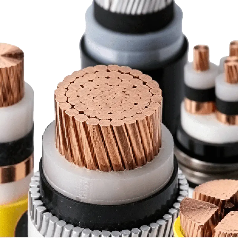
Rated Voltage 3.6/6kV–26/35kV XLPE Insulated Power Cable
3. Cable Construction and Function of Each Layer
The cable structure is designed as a coordinated electrical and mechanical system. Each layer has a specific purpose, and the performance of the finished cable depends on the quality, concentricity, cleanliness, adhesion, and compatibility of all layers.
Layer |
Typical Material |
Main Function |
Conductor |
Copper or aluminum |
Transmits electrical current with low resistance. |
Conductor screen |
Extruded semiconductive compound |
Equalizes the electric field at the conductor-insulation interface. |
Insulation |
Cross-linked polyethylene |
Provides the primary dielectric barrier between the conductor and earth or screen. |
Insulation screen |
Extruded semiconductive compound |
Controls the outer electric field and provides a reliable interface for the metallic screen. |
Metallic screen |
Copper tape or copper wires |
Provides a grounding and fault-current path and assists electric-field control. |
Filling and binding |
Non-hygroscopic filler and non-woven tape |
Maintains the cable shape and reduces moisture-related risks. |
Inner sheath |
PVC, PE, or other specified material |
Separates cores from armoring where an additional barrier is needed. |
Armoring |
Steel tape or steel wire |
Improves resistance to external compression, impact, tensile forces, or pulling forces. |
Outer sheath |
PVC or PE |
Protects the cable against abrasion, moisture, corrosion, and environmental exposure. |
3.1 Conductor Options
Copper conductors provide high electrical conductivity, excellent flexibility, and strong short-circuit performance for a given cross-sectional area. They are often selected where space is limited, where connection compactness is important, or where high conductivity is a priority.
Aluminum conductors offer lower material density and can reduce cable weight. They are frequently selected for long distribution routes and projects where overall cable mass and material cost are important considerations. Aluminum conductor designs require suitable terminations, correct jointing practices, and appropriate attention to oxidation and connection torque.
Available conductor cross-sectional areas generally range from 25mm² to 1000mm² for single-core copper and aluminum constructions, while three-core cables are commonly available from 25mm² or 50mm² up to 500mm², depending on voltage class, conductor material, and cable type. Production availability should be confirmed for each project specification.
3.2 Conductor and Insulation Screens
In medium- and high-voltage cable manufacturing, screen quality is essential. The conductor screen must be smooth, continuous, and closely applied to avoid localized electric-field concentration. The insulation screen must also be uniform and properly bonded to the insulation interface.
Irregularities, contamination, voids, protrusions, or poor interface contact can increase electrical stress and create conditions that may lead to partial discharge. For this reason, screen compounds, insulation materials, extrusion conditions, temperature control, line speed, and cleanliness are carefully managed during production.
3.3 Metallic Screen and Grounding Function
Copper tape screens are suitable for many standard cable constructions. Copper wire screens can provide increased cross-sectional area for fault-current conduction and may be selected for higher voltage classes or larger conductor sizes. For 21/35kV and 26/35kV cables, and for certain cables above 500mm² nominal conductor cross-section, copper wire shielding may be used according to the design requirement.
The metallic screen must be connected to the grounding system in accordance with the installation design. Bonding arrangements, induced voltage, circulating current, screen losses, and fault-current duration should be evaluated by the system designer. Incorrect screen bonding can affect safety and cable ampacity.
4. Voltage Classes and System Selection
Cable voltage must match the operating conditions of the power system. The three principal voltage designations are U0, U, and Um.
U0 is the rated power-frequency voltage between the conductor and earth or metallic screen for which the cable is designed. U is the rated power-frequency voltage between conductors. Um is the maximum value of the highest system voltage that the equipment can withstand.
The selected cable should be appropriate for the system grounding arrangement, expected earth-fault duration, insulation coordination, switching conditions, and overvoltage exposure. Voltage selection should not be based solely on the normal line-to-line operating voltage.
Nominal System Voltage U (kV) |
Maximum System Voltage Um (kV) |
U0, First-Class System (kV) |
U0, Second-Class System (kV) |
1 |
1.2 |
0.6 |
0.6 |
3 |
3.6 |
1.8 |
3.6 |
6 |
7.2 |
3.6 |
6 |
10 |
12 |
6 |
8.7 |
15 |
17.5 |
8.7 |
12 |
20 |
24 |
12 |
18 |
35 |
42 |
21 |
26 |
First-class cable systems are generally intended for systems where a single-phase earth fault is cleared within a short period. The supplied technical information identifies a maximum individual earth-fault duration of one minute, with an aggregate limit of 125 hours in one year. Second-class cable systems are intended for conditions involving longer or more frequent earth faults and require stronger insulation coordination.
Because actual system requirements can vary, the cable voltage class should be confirmed by the electrical engineer, utility specification, or applicable standard before ordering. Special operating conditions may require a higher U0 rating even where the normal line voltage appears suitable for a lower rating.
5. Standard Cable Types and Applications
The cable family includes unarmored and armored constructions with copper or aluminum conductors and PVC or PE outer sheaths. The principal designations include YJV, YJLV, YJY, YJLY, YJV22, YJLV22, YJV23, YJLV23, YJV32, YJLV32, YJV33, and YJLV33.
Type |
Construction |
Typical Application |
YJV |
Copper conductor, XLPE insulation, PVC sheath |
Indoor, tunnel, and direct-burial installation where external mechanical forces are limited. |
YJLV |
Aluminum conductor, XLPE insulation, PVC sheath |
Weight-sensitive distribution routes and general fixed installations. |
YJY |
Copper conductor, XLPE insulation, PE sheath |
Installations requiring a PE outer sheath and suitable environmental resistance. |
YJLY |
Aluminum conductor, XLPE insulation, PE sheath |
Long distribution routes where reduced weight and PE sheath performance are beneficial. |
YJV22 |
Copper conductor, XLPE insulation, steel tape armor, PVC sheath |
Routes requiring protection against certain longitudinal and external mechanical forces. |
YJLV22 |
Aluminum conductor, XLPE insulation, steel tape armor, PVC sheath |
Armored distribution systems with aluminum conductors. |
YJV23 and YJLV23 |
Steel tape armor with PE sheath |
Installations requiring armored construction and a PE outer sheath. |
YJV32 and YJLV32 |
Fine steel wire armor with PVC sheath |
Installations requiring external mechanical protection and a defined pulling capability. |
YJV33 and YJLV33 |
Fine steel wire armor with PE sheath |
Armored installations requiring a PE outer sheath. |
Single-core armored cables require special consideration because magnetic materials can cause induced losses and heating when used around a single alternating-current conductor. The armor material, bonding method, installation arrangement, and current rating must therefore be evaluated. A single-core cable should not be installed in a magnetic duct unless the design specifically addresses this issue.
6. Manufacturing Process for High-Voltage XLPE Cable
Reliable high-voltage cable performance begins with a controlled manufacturing process. Electrical insulation quality cannot be guaranteed by final inspection alone. Material selection, process stability, equipment calibration, environmental cleanliness, dimensional control, and online monitoring must work together throughout production.
6.1 Conductor Preparation
Manufacturing begins with high-quality copper or aluminum rod and conductor materials that comply with the specified electrical and mechanical requirements. The conductor is drawn, compacted, stranded, and formed to the required cross-sectional area and flexibility class.
Conductor resistance is controlled according to GB/T 3956 or the applicable project standard. Conductor geometry must remain stable during subsequent extrusion. Proper compaction reduces voids between wires, improves dimensional consistency, and supports the formation of a uniform conductor screen.
For large cross-sectional conductors, manufacturing control is especially important because small geometric deviations can affect screen uniformity, cable diameter, bending behavior, and the final installation process. Online dimensional monitoring and process inspection help detect deviations at an early stage.
6.2 Triple Extrusion of Screens and Insulation
Medium- and high-voltage XLPE cables are commonly produced using a controlled extrusion process in which the conductor screen, XLPE insulation, and insulation screen are applied in a coordinated sequence. A clean and stable production environment is important because microscopic contamination at the insulation interfaces can increase partial discharge risk.
The XLPE compound is processed under carefully controlled temperature, pressure, and line-speed conditions. Insulation thickness, eccentricity, surface quality, and interface bonding are monitored to ensure that the electrical field remains uniform around the conductor.
Cross-linking converts the polyethylene insulation into a thermoset structure. The cross-linking process must be adequately controlled so that the insulation achieves the required thermal and electrical properties without excessive residual by-products or defects. After cross-linking, the cable is cooled and inspected before additional layers are applied.
6.3 Degassing and Insulation Conditioning
After cross-linking, insulation may contain residual by-products that must be reduced through controlled conditioning or degassing. Effective degassing helps stabilize the insulation and supports reliable partial-discharge performance.
The duration and conditions of this stage depend on the cable size, insulation thickness, production process, and manufacturer’s technical requirements. Careful conditioning is particularly important for higher voltage classes and large cross-sectional cables.
6.4 Metallic Screening
Following the insulation system, the metallic screen is applied. Copper tape may be helically wrapped, while copper wires may be arranged around the insulation screen and secured with suitable binders. Screen coverage, contact, overlap, resistance, and mechanical stability are checked.
The screen design is selected according to short-circuit current, earth-fault duration, grounding configuration, voltage level, and customer requirements. For large cables and higher voltage classes, a copper wire screen may provide a greater metallic cross-section than a basic copper tape screen.
6.5 Core Assembly and Sheathing
For three-core cables, the insulated and screened cores are laid up with suitable fillers and binding tapes. Non-hygroscopic materials help maintain cable geometry while reducing the risk of moisture absorption. An inner sheath may be applied before armoring when the design requires additional separation or protection.
For armored products, steel tape or steel wire is applied with controlled tension and lay direction. Steel tape armor improves resistance to external pressure, while steel wire armor is better suited to applications requiring tensile strength or defined pulling capability.
The outer sheath is then extruded from PVC or PE compound. Sheath thickness, surface condition, concentricity, color, marking, and spark-test performance are inspected. Cable markings typically identify the manufacturer, product type, voltage rating, conductor size, standard, and manufacturing information.
6.6 Online Monitoring and Quality Control
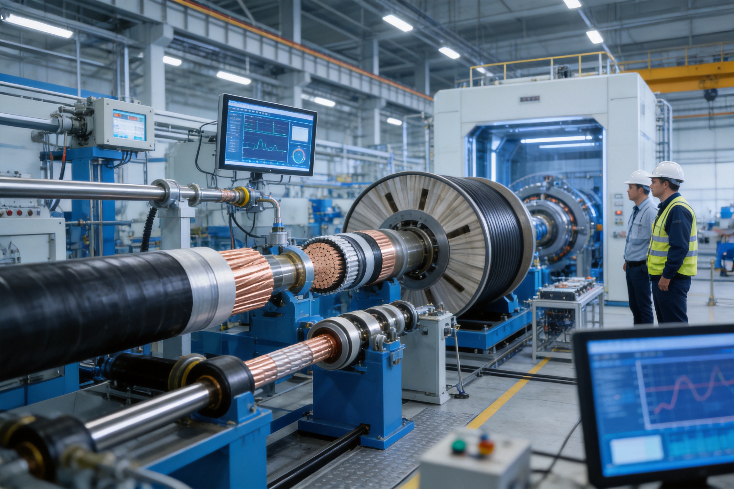
Wuxi Guanghuan Cable Co., Ltd. operates more than 70 production and testing lines and uses equipment such as online eccentricity monitors, high-voltage series-resonance test systems, and partial-discharge detectors. These tools support process control from conductor production through insulation extrusion, screening, sheathing, and final testing.
Online eccentricity monitoring is valuable because insulation thickness must remain evenly distributed around the conductor. Excessive eccentricity can reduce the effective insulation margin on one side of the cable and create an uneven electric field.
High-voltage test equipment verifies insulation withstand capability, while partial-discharge detection helps identify internal electrical defects that may not be visible through ordinary dimensional inspection. Combining online monitoring with laboratory testing creates a stronger quality assurance system than relying on a single final test.
7. Testing and Technical Verification
The product is manufactured in accordance with GB/T 12706, including the provisions applicable to cables rated from 6kV to 30kV and cables rated at 35kV. Production can also be organized according to IEC, British Standards, German Standards, American Standards, or other specified requirements when requested by the customer.
7.1 Conductor Resistance Test
Conductor direct-current resistance is measured at 20°C and evaluated against the relevant conductor standard. Low resistance supports efficient transmission and helps limit conductor losses and operating temperature. The supplied data includes resistance reference values for copper and aluminum conductors from 25mm² to 630mm².
For example, the listed maximum resistance at 20°C is 0.727Ω/km for a 25mm² copper conductor and 1.20Ω/km for a 25mm² aluminum conductor. At 630mm², the corresponding values are listed as 0.0283Ω/km for copper and 0.0469Ω/km for aluminum. Actual production values depend on conductor design and the applicable standard.
7.2 Power-Frequency Withstand Test
The power-frequency AC voltage test evaluates whether the cable insulation can withstand a specified voltage for five minutes. The test voltage varies by cable voltage class. The supplied technical information lists test values from 12.5kV for 3.6/6kV cable up to 91kV for 26/35kV cable under the stated test arrangement.
A four-hour AC withstand test may also be applied. This longer test provides additional verification of insulation integrity. For 21/35kV and 26/35kV cables, alternative power-frequency test conditions may be used upon request, including 2.5U0 for 30 minutes or 3.5U0 for five minutes, subject to the governing standard and agreed specification.
7.3 Partial Discharge Test
Partial discharge is a localized electrical discharge that does not completely bridge the insulation between the conductor and the screen. It can be associated with voids, contamination, protrusions, interface defects, or other imperfections in the insulation system.
The stated requirement is that the maximum partial discharge at 1.73U0 does not exceed 5pC. This is a demanding diagnostic criterion for medium- and high-voltage cable. Low partial-discharge performance supports long-term reliability by reducing the risk of progressive insulation degradation.
7.4 Impulse Voltage Test
Impulse testing verifies resistance to transient overvoltages, including lightning-related surges and switching impulses. Listed impulse test levels range from 60kV for 3.6/6kV cable to 250kV for 26/35kV cable.
Impulse withstand capability is important for cables connected to overhead lines, substations, transformers, generators, and other equipment exposed to transient disturbances. The cable system should also be coordinated with surge arresters and the insulation levels of connected equipment.
7.5 Mechanical and Dimensional Testing
Mechanical and dimensional checks include conductor size, insulation thickness, screen dimensions, sheath thickness, cable diameter, armor coverage, tensile characteristics, elongation, and bending performance. Depending on the standard and product construction, additional tests may include thermal aging, water penetration, sheath integrity, armor resistance, and flammability-related evaluations.
Factory testing confirms the condition of the manufactured product, but transport, storage, installation, jointing, and termination can also influence cable performance. A complete quality program therefore includes installation instructions, drum inspection, field testing, and appropriate supervision of accessories.
8. Current-Carrying Capacity and Installation Correction
The current-carrying capacity of a cable depends on the balance between heat generated by electrical losses and heat dissipated into the surrounding environment. A cable installed in open air may have a different ampacity from the same cable buried in soil. Multiple cables installed close together may also have a lower allowable current than a single isolated cable.
The reference conditions supplied for rating calculations include a maximum conductor temperature of 90°C, an air temperature of 40°C, a ground temperature of 25°C, soil thermal resistivity of 2.0K·m/W, burial depth of 0.8m, and a single circuit. These are reference conditions rather than universal values. Project-specific calculations should use actual site conditions.
8.1 Air Temperature Correction Factors
Air Temperature (°C) |
20 |
25 |
30 |
35 |
40 |
45 |
50 |
Correction Factor |
1.18 |
1.14 |
1.09 |
1.05 |
1.00 |
0.94 |
0.90 |
As ambient air temperature increases, less thermal margin is available between the cable surface and surrounding air. The permissible current must therefore be reduced. Conversely, a lower air temperature can increase the permissible current relative to the reference condition.
8.2 Soil Temperature Correction Factors
Soil Temperature (°C) |
15 |
20 |
25 |
30 |
35 |
40 |
45 |
Correction Factor |
1.08 |
1.04 |
1.00 |
0.96 |
0.92 |
0.88 |
0.83 |
Soil temperature has a direct effect on heat dissipation. Dry, hot, or thermally resistant soil can significantly reduce the cable’s ability to release heat. For important transmission routes, soil thermal conditions should be determined through reliable site information rather than assumed values.
8.3 Soil Thermal Resistivity
Soil Thermal Resistivity (K·m/W) |
0.8 |
1.0 |
1.5 |
2.0 |
2.5 |
3.0 |
3.5 |
Single-Core Factor |
1.42 |
1.31 |
1.12 |
1.00 |
0.91 |
0.83 |
0.75 |
Three-Core Factor |
1.34 |
1.26 |
1.11 |
1.00 |
0.92 |
0.85 |
0.78 |
Thermal resistivity increases when soil is dry, compacted, or composed of materials with poor heat-transfer characteristics. When cable routes are backfilled, thermally improved soil or approved thermal backfill may help maintain predictable operating conditions.
8.4 Grouping and Parallel Installation
Multiple cables installed in parallel generate overlapping heat fields. The correction factor depends on the number of cables, clear distance, arrangement, burial depth, and whether the installation is in air or soil.
For direct-buried cables with a 100mm clear distance, the supplied factors decrease from 1.00 for one cable to 0.75 for six parallel cables. At a 300mm clear distance, the factor for six cables increases to 0.85. In air, a center distance of one cable diameter, two cable diameters, or three cable diameters produces different correction factors for multiple parallel circuits.
These factors demonstrate why cable spacing should be considered during route design. Increasing spacing can improve heat dissipation, but it may also increase trench width, installation cost, and civil-work requirements. A balanced design should consider both thermal performance and project economics.
9. Installation Requirements and Best Practices
9.1 Minimum Bending Radius
The minimum bending radius is generally not less than 15 times the cable outer diameter for three-core cables and not less than 20 times the cable outer diameter for single-core cables. The actual requirement may be higher for large cross-sectional cables, armored constructions, cold-weather installation, or cables with special screen and sheath designs.
Exceeding the minimum bending radius helps protect the insulation screen, metallic screen, armor, sheath, and conductor. Excessive bending can cause mechanical deformation, screen displacement, sheath damage, or unacceptable stress at joints and terminations.
9.2 Installation Temperature
The ambient temperature during installation should not be lower than 0°C unless a manufacturer-approved procedure allows otherwise. At low temperatures, sheath and insulation materials can become less flexible. Forced bending or impact during cold installation may damage the cable even when the exterior appears intact.
Where winter installation is unavoidable, cable drums may need to be stored in a heated environment before installation, and handling procedures should be adapted to the actual temperature. Heating methods must not damage the sheath or introduce local overheating.
9.3 Cable Pulling
Pulling tension, sidewall pressure, pulling speed, bend radius, and pulling direction should be controlled. For armored cables, the pulling method must be compatible with the armor and manufacturer’s recommended pulling points. For single-core cables, magnetic effects and arrangement must also be considered.
Rollers, bell mouths, corner guides, and suitable pulling equipment can reduce friction and mechanical stress. The cable should not be dragged directly over rough ground, sharp edges, or contaminated surfaces.
9.4 Direct Burial and Trench Installation
Direct-buried cable should be laid on a suitable prepared base, surrounded by compatible backfill, and protected against sharp stones or construction debris. Burial depth, warning tape, protective tiles, ducts, drainage, and separation from other utilities should comply with the project specification and local regulations.
Cable trenches must provide sufficient space for bending, jointing, heat dissipation, inspection, and future maintenance. Water accumulation should be managed through drainage or other suitable measures, particularly where cable joints or terminations are located.
9.5 Joints and Terminations
High-voltage cable accessories are as important as the cable itself. Joints and terminations must maintain conductor continuity, insulation integrity, screen continuity, environmental sealing, and electric-field control. Installation should be performed by trained personnel using approved accessories and controlled procedures.
Contamination, moisture, incorrect stripping dimensions, damaged semiconductive screens, inadequate stress control, and improper torque can lead to premature failure. The cable manufacturer’s installation instructions and the accessory supplier’s procedures should be followed precisely.
10. Advantages Over Competing Cable Technologies
10.1 Compared with Oil-Filled Cable Systems
XLPE cables do not require oil circulation equipment, pressure monitoring systems, or the same level of leak management associated with certain oil-filled cable designs. This can simplify installation, reduce auxiliary infrastructure, and lower the risk of environmental contamination from insulating oil.
The simpler structure is particularly advantageous for urban networks, tunnels, industrial plants, and projects where access for maintenance equipment is limited. XLPE cables can also be supplied in practical drum lengths, reducing the number of joints in some applications.
10.2 Compared with Lower-Temperature Thermoplastic Insulation
The 90°C continuous conductor rating of XLPE provides a higher thermal operating limit than many traditional thermoplastic insulation systems. This may allow higher current transmission or more compact cable routing when all rating factors are properly considered.
The thermoset structure also improves resistance to softening under sustained heat. This is valuable in high-load feeders, transformer connections, industrial distribution systems, and renewable-energy collection networks.
10.3 Compared with Unscreened or Basic Low-Voltage Cables
Medium- and high-voltage XLPE cables use carefully designed semiconductive screens and metallic screens to control the electric field. This makes them suitable for higher system voltages where ordinary low-voltage cable structures would not provide the necessary dielectric coordination.
Screened construction also supports controlled connection to accessories, grounding systems, and protection equipment. It provides a more predictable electrical interface throughout the cable system.
10.4 Flexible Material and Construction Choices
The availability of copper or aluminum conductors, single-core or three-core configurations, PVC or PE sheaths, copper tape or wire screens, and different armor options allows the cable to be matched to a broad range of project conditions.
This flexibility is a practical advantage over products available only in one conductor material or one sheath construction. It allows designers to balance conductivity, weight, cost, mechanical protection, installation method, and environmental resistance.
11. Manufacturing Strengths of Wuxi Guanghuan Cable Co., Ltd.
Wuxi Guanghuan Cable Co., Ltd. was founded in 1998 and is headquartered in Guanlin Town, Yixing City, Jiangsu Province, a region recognized as an important cable-manufacturing center in China. The company covers more than 100,000 square meters, including more than 45,000 square meters of building area, and has registered capital of RMB 400.8 million.
The company operates more than 70 advanced production and testing lines and employs more than 140 people, including more than 30 technical professionals. Its reported annual sales revenue is approximately RMB 2 billion, with annual output value exceeding RMB 3 billion. These resources support both standard production and customized cable development for power, industrial, infrastructure, transportation, and renewable-energy applications.
The company manufactures power cables, electrical equipment wires and cables, bare conductors, overhead insulated cables, high-speed railway and urban rail transit cables, and cables for energy storage, photovoltaic, and wind-power applications. More than 100 product categories and over 30,000 specifications are offered under the registered Liguang brand.
11.1 Integrated Quality Management
Quality management systems include ISO 9001 quality management certification, ISO 14001 environmental management certification, ISO 45001 occupational health and safety certification, and ISO 50001 energy management certification. The company also reports certifications or management-system recognition covering intellectual property, green management, social responsibility, and after-sales service.
This broad management framework is relevant to high-voltage cable production because product consistency depends not only on machinery but also on documented procedures, employee competence, equipment maintenance, material traceability, corrective action, and continuous improvement.
11.2 Testing and Certification Capability
The company reports product certifications and recognition including CCC, TÜV, product carbon footprint, and China Energy-Saving and Environmentally Friendly Product certifications. Its products and manufacturing capabilities have also undergone qualification and capability verification associated with power cable and conductor supply.
For customers purchasing medium- and high-voltage cable, certification should be reviewed together with the exact cable design, voltage class, conductor material, applicable standard, and test certificate. A general company certificate does not replace product-specific verification, but it can demonstrate the manufacturer’s established quality infrastructure.
11.3 Technical Service and Customization
High-voltage cable selection often involves more than choosing a standard catalog number. Customers may require a particular conductor size, screen cross-section, sheath material, armor structure, drum length, fire or environmental performance, or compliance standard.
A manufacturer with broad product coverage and technical staff can help coordinate cable design, current-rating calculations, accessory compatibility, transport packaging, installation guidance, and inspection documentation. This reduces the risk of mismatch between the cable and the overall power system.
12. Typical Applications
12.1 Urban Distribution Networks
Urban power networks often require compact, reliable underground cables that can be installed in ducts, tunnels, trenches, and direct-buried routes. XLPE cables are suitable for feeders connecting substations, distribution cabinets, transformers, and large commercial or residential loads.
12.2 Industrial Installations
Industrial plants may contain motors, transformers, furnaces, pumps, compressors, production lines, and process equipment with significant electrical demand. XLPE cables can provide reliable fixed connections between medium-voltage switchgear and industrial loads.
In chemical, metallurgical, mining, and manufacturing environments, sheath selection and mechanical protection should be based on actual exposure conditions. Armored cables may be appropriate where impact, compression, or pulling forces are expected.
12.3 Infrastructure Projects
Rail transit systems, airports, ports, hospitals, data centers, water-treatment facilities, and large public buildings require dependable power distribution. Cables may need to pass through tunnels, service corridors, vertical shafts, cable trenches, and equipment rooms.
The relatively simple construction and installation flexibility of XLPE cables make them suitable for these complex routes. However, fire performance, smoke requirements, grounding, electromagnetic compatibility, and emergency power arrangements must be reviewed for each project.
12.4 Renewable-Energy and Energy Projects
Photovoltaic plants, wind farms, energy-storage facilities, and other new-energy projects require cables connecting collection systems, transformers, inverters, substations, and grid interfaces. The selected cable must be matched to load profile, fault level, environmental exposure, installation arrangement, and system voltage.
Long cable routes and outdoor installations may benefit from aluminum conductors and PE sheaths, while compact substation or transformer connections may favor copper conductors. The final choice should be based on lifecycle cost rather than material price alone.
13. Product Selection Checklist
Before ordering a 3.6/6kV–26/35kV XLPE insulated power cable, the following technical information should be confirmed:
1. System nominal voltage, maximum system voltage, grounding method, and required U0 rating.
2. Required conductor material, copper or aluminum, and nominal cross-sectional area.
3. Single-core or three-core construction.
4. Required current-carrying capacity under actual installation conditions.
5. Short-circuit current magnitude and duration.
6. Metallic screen material and cross-sectional area.
7. PVC or PE outer sheath requirement.
8. Need for steel tape armor or steel wire armor.
9. Indoor, outdoor, tunnel, trench, duct, well, or direct-burial installation.
10. Soil temperature, soil thermal resistivity, burial depth, and cable grouping.
11. Ambient temperature, solar exposure, ventilation, and adjacent heat sources.
12. Minimum bending radius, pulling tension, drum length, and route geometry.
13. Applicable national, international, utility, or project standard.
14. Required routine, type, sample, and special tests.
15. Compatibility with joints, terminations, transformers, switchgear, and grounding equipment.
14. Frequently Asked Questions
Q1: What does 3.6/6kV–26/35kV mean?
The designation describes the range of rated voltage classes covered by the product family. In U0/U notation, the first value represents the rated voltage between the conductor and earth or metallic screen, while the second value represents the rated voltage between conductors. The exact cable voltage must be selected according to the power-system configuration.
Q2: What is the maximum continuous conductor temperature?
The maximum permissible long-term conductor temperature is 90°C under the stated product characteristics. The actual operating temperature depends on load current, installation environment, grouping, soil conditions, and heat dissipation.
Q3: What is the maximum short-circuit conductor temperature?
During a short circuit with a maximum duration of five seconds, the conductor temperature should not exceed 250°C, provided that the cable is correctly selected and the short-circuit calculation follows the applicable standard.
Q4: Why is XLPE preferred for medium-voltage power cables?
XLPE offers high insulation resistance, strong dielectric performance, low dielectric loss, high operating temperature capability, good mechanical stability, and resistance to many environmental influences. It also enables a relatively compact and maintenance-friendly cable design.
Q5: Should I choose copper or aluminum conductor?
Copper offers higher conductivity and can provide a compact connection for a given current. Aluminum has lower density and can reduce cable weight and material cost. The decision should consider conductor size, route length, installation handling, termination compatibility, voltage drop, losses, and lifecycle economics.
Q6: When is armored cable necessary?
Armoring is considered when the cable must withstand external mechanical pressure, impact, compression, longitudinal force, or pulling force. Steel tape armor and steel wire armor provide different mechanical characteristics, so the selection should match the route and installation method.
Q7: Can these cables be directly buried?
Yes. Suitable types can be installed directly in the ground, provided that the cable construction, outer sheath, armor, burial depth, bedding, backfill, separation, drainage, and protection comply with the project requirements.
Q8: What is the purpose of the metallic screen?
The metallic screen helps control the electric field, provides a connection to the grounding system, and can carry charging, induced, or fault current depending on the system design. Its cross-sectional area and bonding arrangement must be selected according to the electrical design.
Q9: What is partial discharge, and why is it tested?
Partial discharge is a localized electrical discharge within or around the insulation system that does not completely bridge the insulation. It can indicate defects or weak points. The stated maximum partial-discharge requirement is 5pC at 1.73U0.
Q10: What standards can be followed?
The product is manufactured according to the relevant sections of GB/T 12706. Production can also be arranged according to IEC, BS, DIN, ASTM, or other customer-specified standards, subject to technical review and agreement.
Q11: How should cable ampacity be calculated?
Start with the applicable base rating, then apply correction factors for air or soil temperature, soil thermal resistivity, burial depth, cable spacing, parallel circuits, installation arrangement, and other relevant conditions. A qualified electrical designer should perform the final calculation.
Q12: What information should be provided for a quotation?
Provide voltage rating, conductor material and size, number of cores, cable type, sheath material, armor requirement, metallic screen specification, approximate quantity, installation method, applicable standard, delivery length, and any required tests or certificates.
15. Conclusion
Rated voltage 3.6/6kV–26/35kV XLPE insulated power cables provide a dependable solution for medium- and high-voltage transmission and distribution. Their cross-linked polyethylene insulation combines high electrical strength, low dielectric loss, thermal stability, mechanical performance, and resistance to many environmental conditions.
The cable family supports copper and aluminum conductors, single-core and three-core designs, PVC and PE sheaths, copper tape and copper wire screens, and steel tape or steel wire armor. This range enables engineers to match the cable to different current levels, installation routes, mechanical conditions, grounding systems, and project standards.
Product reliability depends on more than the nominal cable type. It is also determined by conductor quality, screen uniformity, insulation cleanliness, extrusion control, cross-linking, degassing, metallic-screen design, sheath integrity, factory testing, and installation workmanship. The use of online eccentricity monitors, high-voltage test systems, partial-discharge detectors, and comprehensive management systems strengthens manufacturing consistency.
With extensive production capacity, technical personnel, broad product coverage, and experience in power and specialized cable manufacturing, Wuxi Guanghuan Cable Co., Ltd. is positioned to provide standard and customized XLPE cable solutions for utilities, industrial users, infrastructure developers, energy companies, and engineering contractors.
For the best result, cable selection should be completed through a coordinated review of electrical voltage, load current, short-circuit conditions, installation environment, mechanical requirements, standards, accessories, and lifecycle cost. When these factors are correctly addressed, XLPE insulated power cable can provide safe, efficient, and durable service in demanding distribution systems.
References
GB/T 12706, Power Cables with Extruded Insulation and Their Accessories for Rated Voltages from 1kV to 35kV.
GB/T 3956, Conductors of Insulated Cables.
IEC 60502-2, Power Cables with Extruded Insulation and Their Accessories for Rated Voltages from 6kV to 30kV.
IEC 60840, Power Cables with Extruded Insulation and Their Accessories for Rated Voltages Above 30kV up to 150kV.
IEC 60228, Conductors of Insulated Cables.
Technical product information for 3.6/6kV–26/35kV XLPE insulated power cables.
Manufacturer quality-management, testing, production-capability, and company information supplied for this article.
Product: Rated Voltage 3.6/6kV–26/35kV XLPE Insulated Power Cable

-
Rated Voltage 3.6/6kV–26/35kV XLPE Insulated Power Cable
-
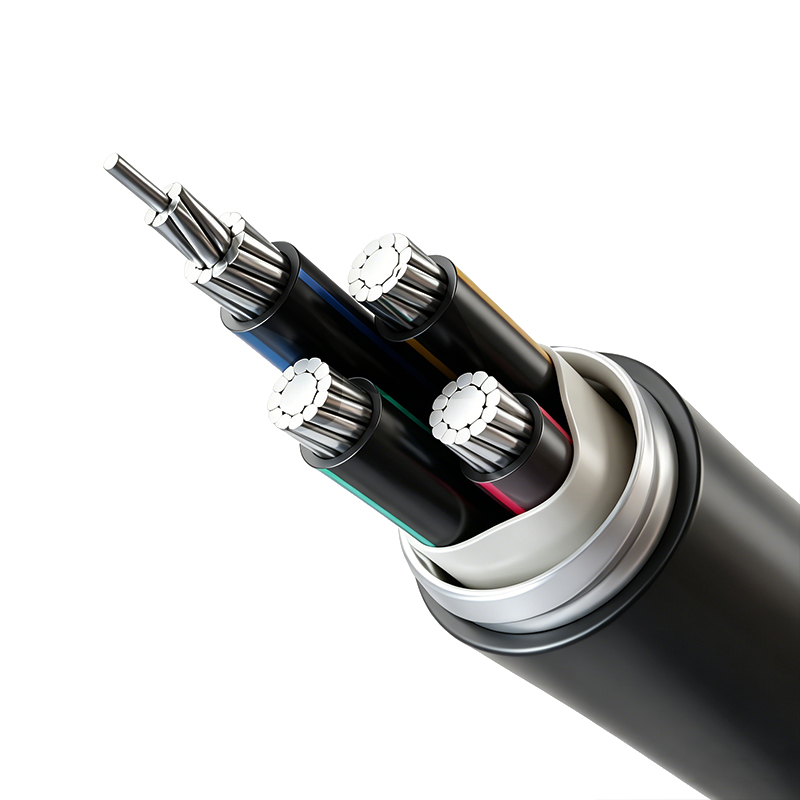
Aluminum Alloy Conductor Plastic Insulated Power Cable (Rated Voltage up to 26/35kV)
-
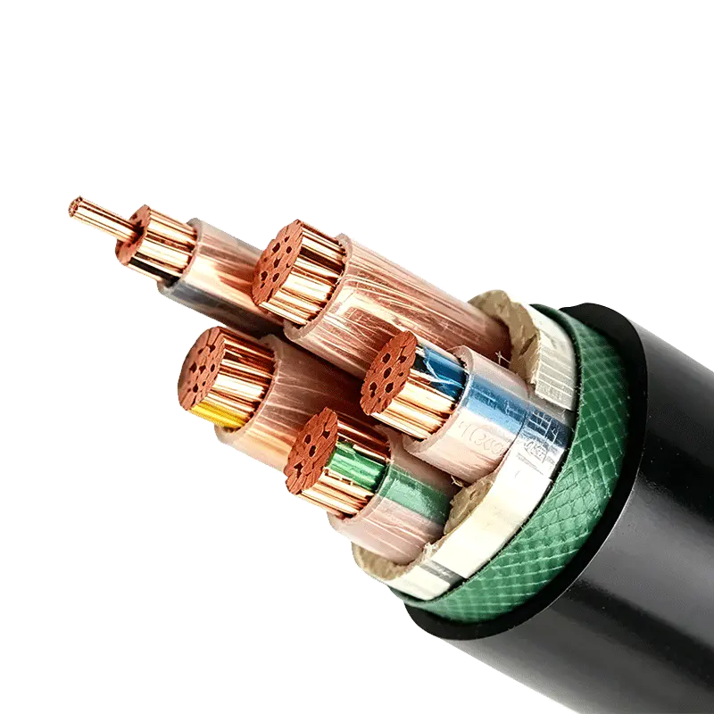
Rated Voltage 0.6/1kV XLPE Insulated Power Cable
-
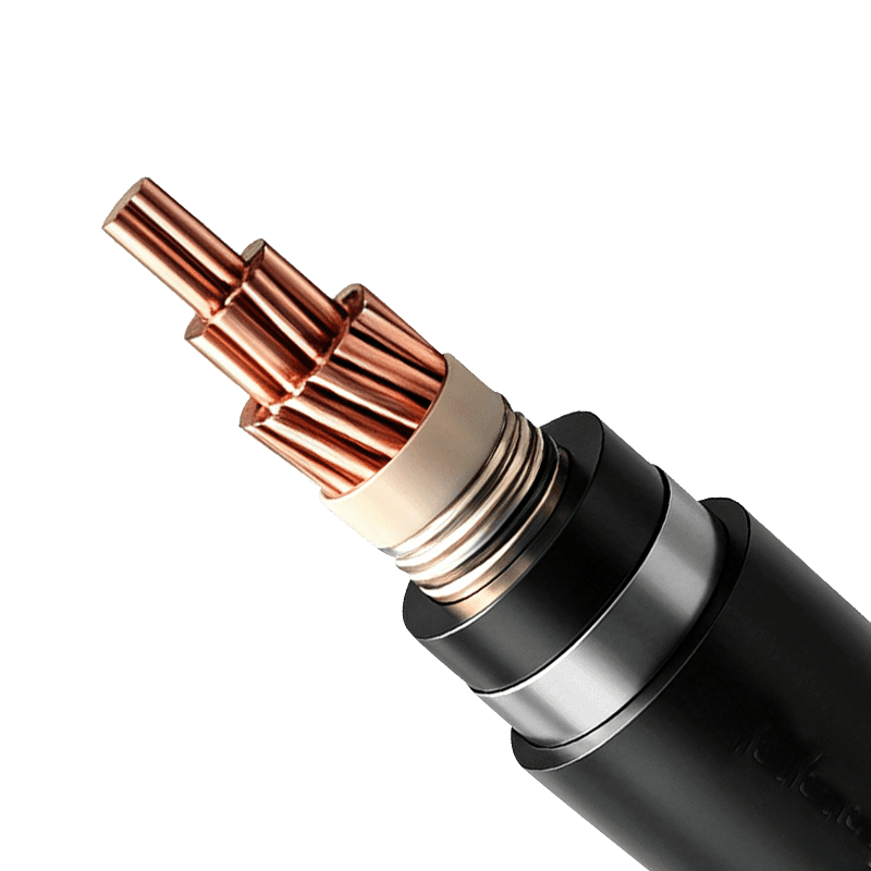
Power Cable for Subway and Urban Rail Transit (Rated Voltage 35kV)
-
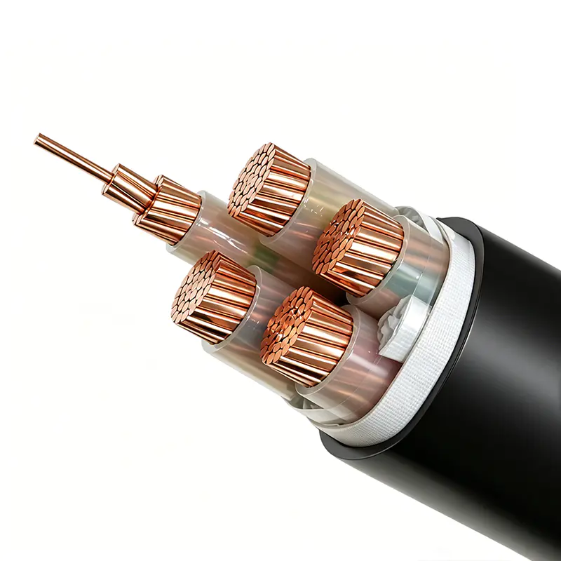
Rated Voltage 1.8/3kV XLPE Insulated Power Cable

Copyright © Wuxi Guanghuan Cable Co., Ltd. All Rights Reserved. Power Cables Manufacturer Electrical Wire And Cable Factory

