


 English
 中文简体
 русский
 Español
 عربى

Rated Voltage 1.8/3kV XLPE Insulated Power Cable: Design, Performance, Applications, and Manufacturing Advantages
Content
- 1 1. Product Overview
- 2 2. Why XLPE Insulation Is Important
- 3 3. Electrical and Thermal Performance
- 4 4. Main Cable Construction
- 5 5. Key Technical Parameters
- 6 6. Advantages Compared with Conventional 0.6/1kV Cables
- 7 7. Applications in Industrial Power Systems
- 8 8. Manufacturing Process and Quality Control
- 9 9. Manufacturer Capability and Production Strength
- 10 10. Product Advantages for Project Buyers
- 11 11. Installation Recommendations
- 12 12. Selection Guidance
- 13 13. Inductance and Capacitance Reference Data
- 14 14. Maintenance and Service Reliability
- 15 15. Frequently Asked Questions
- 15.1 Q1: What does the 1.8/3kV rating mean?
- 15.2 Q2: Why is XLPE used instead of ordinary polyethylene?
- 15.3 Q3: Can this cable replace a 0.6/1kV cable?
- 15.4 Q4: Is the cable suitable for direct burial?
- 15.5 Q5: What is the minimum bending radius?
- 15.6 Q6: What conductor materials are available?
- 15.7 Q7: What is the difference between steel tape and steel wire armor?
- 15.8 Q8: Can the cable be used in coal mines?
- 15.9 Q9: What installation temperature is permitted?
- 15.10 Q10: How is current-carrying capacity determined?
- 15.11 Q11: Does a larger conductor always provide better performance?
- 15.12 Q12: What tests are performed on the cable?
- 15.13 Q13: Can the cable be customized?
- 15.14 Q14: Which standards apply to the product?
- 15.15 Q15: Why is manufacturer testing capability important?
- 16 16. Conclusion
- 17 References
- 18 Product: Rated Voltage 1.8/3kV XLPE Insulated Power Cable
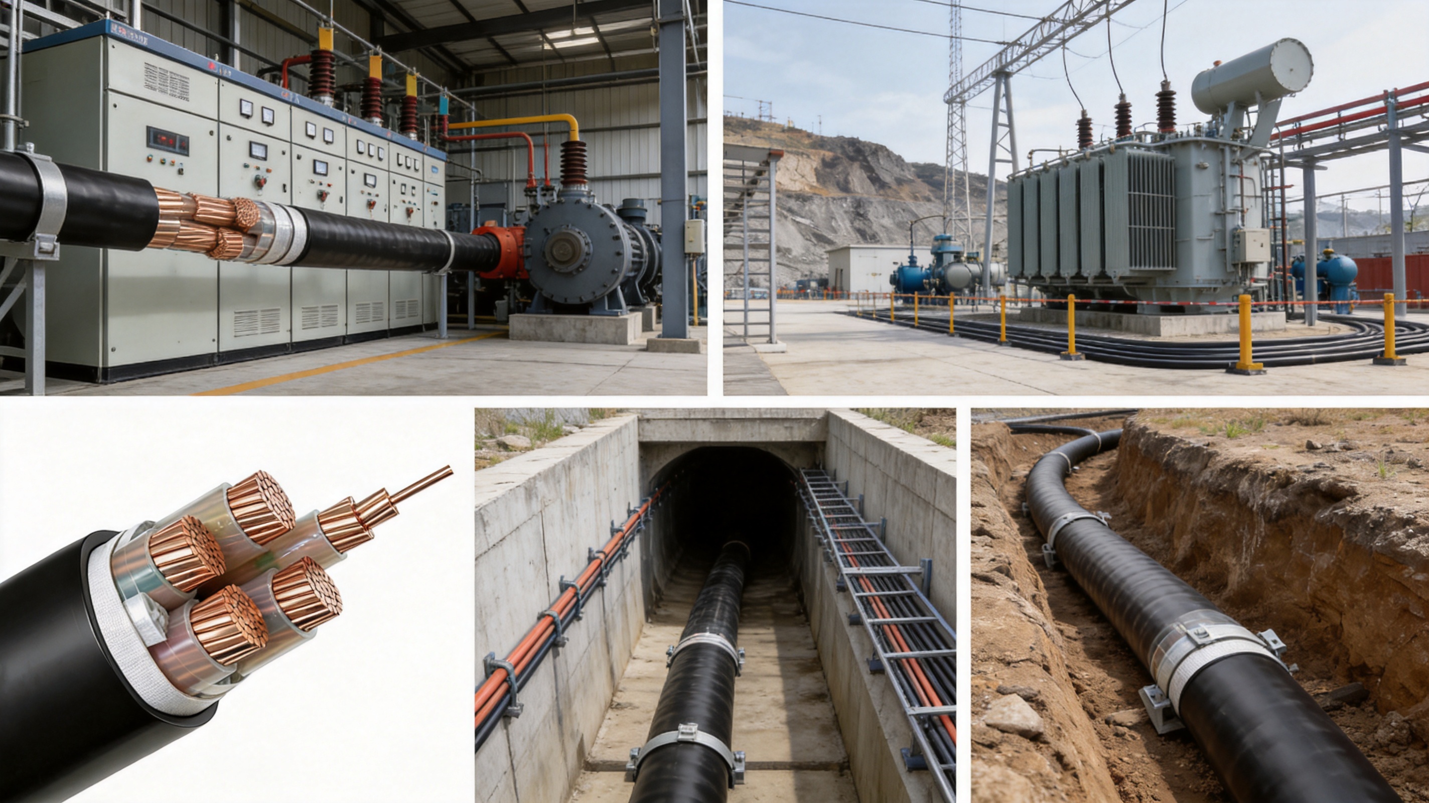
The 1.8/3kV XLPE insulated power cable is designed for power transmission and distribution applications that require a higher insulation level than conventional low-voltage cable systems. Positioned between 0.6/1kV low-voltage cables and many medium-voltage cable systems, this product provides a practical solution for industrial installations, equipment power supplies, mining facilities, energy projects, tunnels, cable trenches, and other fixed installations where reliable electrical performance is essential.
By using cross-linked polyethylene as the primary insulation material, the cable achieves improved thermal stability, mechanical strength, insulation resistance, and long-term operating reliability. Its rated voltage of 1.8/3kV enables it to withstand higher electrical stress than ordinary 0.6/1kV cables, while its structural configuration remains suitable for a wide range of industrial distribution systems.
The cable can be manufactured with copper or aluminum conductors, PVC or PE outer sheaths, and optional steel tape or steel wire armoring. This flexibility allows engineers to select a configuration according to current-carrying requirements, installation conditions, mechanical protection needs, environmental exposure, and project specifications.
Manufacturing quality is equally important. A reliable 1.8/3kV cable depends not only on the nominal voltage rating but also on conductor quality, insulation uniformity, dimensional accuracy, concentricity, shielding or protective construction where required, and the effectiveness of electrical and mechanical testing. Advanced cable production and testing capabilities help ensure that the finished product performs consistently throughout its service life.
1. Product Overview
The rated voltage 1.8/3kV XLPE insulated power cable is a fixed-installation power cable intended for the transmission and distribution of electrical energy. The designation 1.8/3kV indicates the rated voltage between conductor and earth, U0, and the rated voltage between conductors, U, respectively.
In practical terms, the cable is intended for systems where the voltage level is higher than standard low-voltage distribution but where a compact and flexible industrial power cable remains desirable. It may be used to connect industrial switchgear, transformers, motors, variable-frequency equipment, production lines, pump stations, mining equipment, and other electrical loads.
The cable uses XLPE insulation. During production, polyethylene is converted from a primarily linear molecular structure into a three-dimensional cross-linked network through a chemical or physical cross-linking process. This molecular transformation gives the insulation greater resistance to heat deformation and improves its ability to remain stable under electrical and mechanical stress.
Compared with conventional thermoplastic insulation, XLPE can support a higher maximum continuous conductor temperature. For this product, the maximum permissible long-term conductor operating temperature is 90°C. Under short-circuit conditions lasting no more than five seconds, the maximum conductor temperature can reach 250°C, subject to applicable design and standard requirements.
The product may be supplied as an armored or non-armored cable. Non-armored constructions are suitable where the cable is installed in protected indoor spaces, cable trays, conduits, or other locations with limited mechanical risk. Armored constructions provide additional protection against compression, impact, pulling forces, and other mechanical stresses encountered in direct burial, tunnels, shafts, industrial sites, and mining environments.
2. Why XLPE Insulation Is Important
Insulation is one of the most important components of any power cable. It separates the energized conductor from other conductors, metallic layers, earth, and surrounding structures. It must withstand electrical stress while also resisting heat, moisture, mechanical movement, aging, and environmental influences.
XLPE insulation offers several advantages for higher-voltage industrial power cables. Its cross-linked molecular structure reduces the tendency of the material to soften or deform under heat. This characteristic helps the cable maintain its electrical dimensions and insulation performance when operating at elevated temperatures.
The 90°C continuous conductor temperature rating provides a useful operating margin compared with many conventional low-voltage cable designs. When properly selected and installed, the cable can carry higher loads within its permissible thermal limits. The actual current-carrying capacity still depends on conductor size, installation method, ambient temperature, soil conditions, grouping, and other correction factors.
XLPE also provides strong insulation resistance and low dielectric loss. Low dielectric loss helps reduce energy dissipation within the insulation system. This is particularly valuable in industrial power distribution, where cable routes may be long and operating loads may vary considerably.
Another advantage is dimensional and thermal stability. Stable insulation thickness and consistent material properties are essential for maintaining the cable’s rated voltage performance. Modern extrusion and cross-linking processes help produce an insulation layer with controlled thickness, smooth surfaces, and reliable concentricity around the conductor.
Compared with cables using ordinary thermoplastic insulation, XLPE insulated cables can offer better resistance to thermal aging and improved performance under overload or short-circuit conditions. These characteristics make them suitable for demanding industrial applications where downtime, insulation failure, and maintenance interruptions must be minimized.
3. Electrical and Thermal Performance
The principal electrical performance advantage of the 1.8/3kV design is its higher insulation withstand capability compared with 0.6/1kV power cable. Industrial networks may experience voltage fluctuation, switching transients, motor starting currents, and other electrical stresses. A cable with a higher rated insulation level provides a more appropriate margin for these conditions when selected according to the system design.
The cable is tested using an AC withstand voltage of 6.5kV for five minutes without breakdown, according to the stated product parameters. This test places a controlled electrical stress on the completed cable and helps verify the integrity of the insulation system. The test result is not a substitute for correct system design, but it is an important indicator of manufacturing quality and dielectric reliability.
Partial discharge performance is also important for cables operating at elevated voltage levels. Partial discharge can occur when localized defects, voids, impurities, or irregularities create regions of intensified electrical stress. If not controlled, repeated partial discharge may gradually degrade insulation. The cable is designed so that, at 1.73U0, the maximum partial discharge remains within the applicable specified limit.
Conductor resistance is controlled in accordance with GB/T 3956 requirements at 20°C. Low and consistent conductor resistance helps reduce I²R losses, limit voltage drop, and improve overall power transmission efficiency. The exact resistance depends on conductor material, cross-sectional area, conductor class, compactness, and manufacturing tolerances.
The maximum long-term conductor temperature is 90°C. This temperature rating supports higher load capacity than many standard low-voltage thermoplastic cable designs, although the final ampacity must always be calculated using the installation conditions. A cable installed in open air may have a different current-carrying capacity from the same cable installed in soil, a conduit, a tunnel, or a group of parallel cables.
During a short circuit lasting no more than five seconds, the conductor temperature must not exceed 250°C. This short-term thermal capability supports system protection coordination and allows the cable to withstand the heat generated during a properly cleared fault. Protective devices should be selected so that fault duration remains within the cable’s permissible limit.
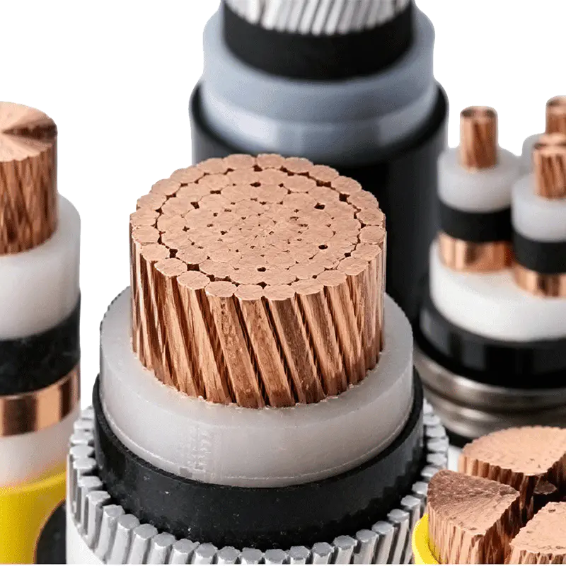
4. Main Cable Construction
4.1 Conductor
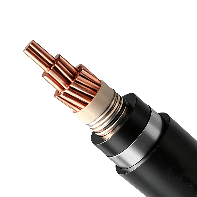
The conductor may be manufactured from high-purity copper or aluminum. Copper provides excellent electrical conductivity, good flexibility, and strong connection performance. Aluminum offers lower density and can reduce cable weight, which may be beneficial for long routes, large cross-sections, elevated installations, and projects where handling and support requirements are significant.
Conductor construction is designed in accordance with applicable GB/T 3956 requirements. Depending on the specification, the conductor may use a compact stranded construction to achieve a favorable balance between flexibility, conductivity, diameter, and ease of installation.
Accurate stranding and compacting are important manufacturing operations. They help maintain consistent conductor geometry, reduce unnecessary voids, improve dimensional uniformity, and support even application of the insulation layer. Conductor quality also affects termination reliability because an irregular or contaminated conductor may create connection resistance or localized heating.
4.2 XLPE Insulation
The XLPE insulation is applied by controlled extrusion. The insulation thickness is optimized for the 1.8/3kV voltage level and must remain uniform around the conductor. Consistent thickness is essential because a thin section can create an area of increased electrical stress, while excessive variation can affect the overall dimensions and performance of the cable.
During extrusion and cross-linking, production conditions such as material cleanliness, temperature, pressure, line speed, and cooling must be carefully controlled. The use of online monitoring equipment can help identify eccentricity or dimensional variation during production rather than after the cable has been completed.
A smooth and stable insulation surface reduces the possibility of electrical stress concentration. The insulation must also be free from visible defects, foreign particles, moisture, and voids that could affect long-term dielectric performance.
4.3 Filling and Binding Components
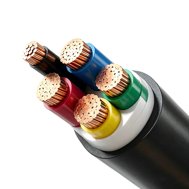
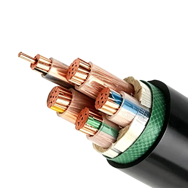
For multi-core cable constructions, non-hygroscopic filling materials may be used to maintain the roundness of the cable and support the relative position of the insulated cores. Maintaining a stable circular profile helps improve handling, sheath application, bending behavior, and dimensional consistency.
Non-woven binding tape can be applied to secure the cores and filling materials before the inner sheath or outer sheath is extruded. The binding layer helps keep the assembly stable during subsequent manufacturing stages and installation.
4.4 Inner Sheath
An inner sheath may be included in armored designs. It separates the insulated cores from the armor and provides an additional protective layer. The inner sheath can help reduce mechanical interaction between the armor and the insulation system while also improving the overall shape and integrity of the cable.
The selection of inner sheath material and thickness depends on the cable construction, armor type, installation environment, and applicable standards. It is especially useful where the cable must withstand mechanical stresses during installation or service.
4.5 Armoring
Steel tape armoring is suitable where compression resistance and general mechanical protection are important. It can help protect the cable from external pressure, impact, and damage during installation in trenches, ducts, industrial floors, or direct-burial routes.
Steel wire armoring is selected when greater tensile strength is required. This construction may be preferred for vertical installations, shafts, difficult pulling routes, or locations where the cable may experience longitudinal mechanical forces.
Armor selection should be based on engineering calculations and installation conditions rather than treated as a standard accessory. The correct armor can protect the cable during construction and reduce the risk of damage caused by external mechanical forces.
4.6 Outer Sheath
The outer sheath provides the first line of protection against moisture, abrasion, chemicals, sunlight, corrosion, aging, and flame propagation, depending on the material and product design. PVC and PE sheath materials can be selected according to project requirements.
PVC is widely used because of its balanced mechanical properties, processability, cost efficiency, and general environmental resistance. PE may be selected where enhanced moisture resistance, weather resistance, or specific mechanical properties are needed.
For mining and other high-risk environments, flame-retardant sheath constructions may be specified. Such designs must be manufactured and tested according to the relevant product and industry requirements, including applicable coal mine cable standards where required.
The sheath must have a uniform thickness and a smooth surface without cracks, bubbles, excessive roughness, or other defects. A stable outer sheath protects the internal structure and supports reliable service in demanding installation conditions.
5. Key Technical Parameters
Parameter |
Specified Value or Description |
Rated voltage |
1.8/3kV |
Maximum long-term conductor temperature |
90°C |
Maximum short-circuit conductor temperature |
250°C for a maximum duration of five seconds |
Minimum installation temperature |
0°C; preheating is required below this temperature |
Minimum bending radius |
Not less than 15 times the cable outer diameter |
Conductor standard |
GB/T 3956 requirements at 20°C |
AC withstand test |
6.5kV for five minutes without breakdown |
Insulation material |
Cross-linked polyethylene |
Conductor materials |
Copper or aluminum |
Armor options |
Steel tape or steel wire, according to construction requirements |
Sheath options |
PVC or PE, with optional flame-retardant designs |
6. Advantages Compared with Conventional 0.6/1kV Cables
The most direct advantage of the 1.8/3kV cable is its higher rated voltage. In industrial applications, selecting a cable with an appropriate voltage class helps ensure that the insulation system is matched to the electrical network. The cable can provide a more suitable margin where voltage fluctuations, motor starting conditions, or switching events are more demanding than those found in simple low-voltage circuits.
For the same conductor cross-section, the higher voltage level can support the transmission of more power under suitable system conditions. It may also permit longer transmission distances before voltage drop becomes excessive. The actual result depends on load current, power factor, conductor resistance, route length, operating temperature, and system configuration, but the higher voltage class can improve the overall design options.
The 90°C XLPE operating temperature rating can provide stronger thermal performance than many standard low-voltage cable constructions. This may allow a more compact cable solution for a specified load, although ampacity calculations must be completed for every installation.
The 250°C short-circuit temperature capability provides additional thermal resistance during fault conditions. When coordinated with correctly selected circuit protection, the cable can withstand the short-duration heat generated by a fault without exceeding its specified thermal limit.
The cable’s flexible structural options are another advantage. Users can select copper or aluminum conductors, armored or non-armored constructions, steel tape or steel wire armor, and PVC or PE sheath materials. This allows one product family to serve a broad range of industrial applications rather than requiring an entirely different cable type for every installation.
Compared with lower-rated cables, this product can also reduce the risk of applying an insufficient insulation level to an industrial power circuit. Choosing a cable specifically designed for 1.8/3kV service helps align the cable with the electrical stresses of the system and supports a more robust power distribution design.
Compared with some higher-voltage cable systems, a 1.8/3kV cable can offer a practical and economical solution where the network does not require a more complex medium-voltage construction. It provides a balance between insulation performance, installation convenience, mechanical options, and project cost.
7. Applications in Industrial Power Systems
7.1 Industrial Distribution Networks
The cable is suitable for fixed power distribution within factories, workshops, processing plants, warehouses, and other industrial facilities. It can connect distribution panels, transformers, switchgear, motors, production equipment, and auxiliary systems.
Industrial environments often include high starting currents, frequent switching, vibration, heat, dust, and cable routes with restricted space. XLPE insulation and optional armoring help the cable meet these conditions when the correct construction is selected.
7.2 Large Motors and Variable-Frequency Equipment
Large motors and variable-frequency drives can impose demanding electrical conditions on power cables. Starting currents, rapid load changes, harmonics, and voltage fluctuations should be considered during cable selection. The higher insulation level of the 1.8/3kV cable makes it appropriate for many industrial motor feeder applications within the specified system voltage range.
When used with variable-frequency equipment, the complete system design must also consider electromagnetic compatibility, grounding, shielding requirements, cable length, inverter output characteristics, and termination methods. The cable should be selected according to the equipment manufacturer’s instructions and the electrical design of the installation.
7.3 Mining and Energy Facilities
Mining operations often require cables that can tolerate difficult installation routes, mechanical stress, dust, moisture, and potential flame hazards. An armored and flame-retardant construction can be selected for suitable underground or surface applications, subject to applicable mine safety requirements and certification.
The cable may also be used in energy facilities, auxiliary power systems, pumping stations, substations, generation plants, and industrial utility networks. In each case, the conductor size, sheath material, armor, and installation method should be selected according to the site conditions.
7.4 Tunnels, Cable Trenches, and Shafts
In tunnels and cable trenches, cables may be exposed to limited ventilation, water ingress, confined bending space, and mechanical contact with support structures. The cable’s minimum bending radius, sheath type, armor construction, and grouping arrangement should be reviewed before installation.
Vertical shafts can create additional tensile forces. Steel wire armoring may be appropriate where the cable is subjected to vertical loading, but the installation system should include suitable supports, cleats, clamps, and load-management measures.
7.5 Direct Burial and Outdoor Routes
For direct-burial applications, mechanical protection, moisture resistance, soil thermal resistivity, burial depth, and protection from excavation damage are important considerations. An armored construction and a suitable outer sheath can provide stronger protection than a non-armored design.
Outdoor installations should account for ultraviolet exposure, temperature variation, rain, water accumulation, and possible chemical contamination. PE or specially specified PVC sheath materials may be selected according to the environmental requirements.
8. Manufacturing Process and Quality Control
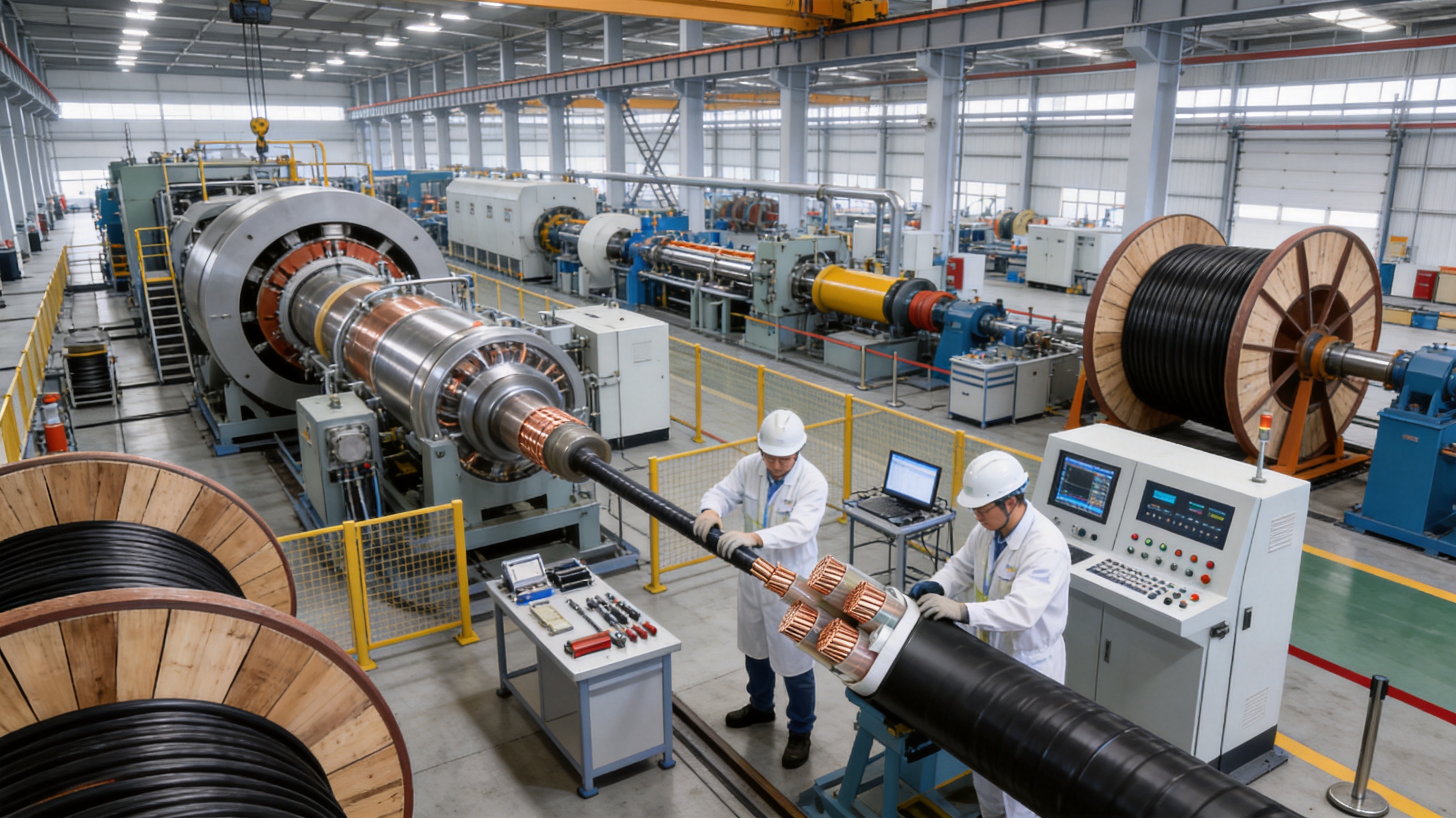
Reliable cable performance begins with a controlled manufacturing process. The production of a 1.8/3kV XLPE cable includes conductor preparation, insulation extrusion, cross-linking, cooling, core assembly, filling and binding, optional inner sheath application, armoring, outer sheath extrusion, marking, testing, and final inspection.
8.1 Raw Material Control
Conductor materials, XLPE insulation compounds, sheath compounds, filling materials, binding tapes, and armor materials must be inspected before production. Material control helps prevent contamination, inconsistent electrical properties, dimensional variation, and premature aging.
XLPE compounds require particular attention because cleanliness and processing stability have a direct effect on dielectric performance. Material storage conditions should protect compounds from moisture, dust, temperature extremes, and contamination.
8.2 Conductor Processing
Copper or aluminum rods are processed through drawing, stranding, and, where applicable, compacting operations. Equipment accuracy and process control help achieve the required conductor resistance and cross-sectional geometry.
Online or in-process inspection may be used to identify diameter variation, surface defects, strand displacement, or other irregularities. Correct conductor geometry supports uniform insulation application and reliable terminal connections.
8.3 Controlled Insulation Extrusion
The insulation is applied using extrusion equipment designed to maintain stable temperature, pressure, material flow, and line speed. A concentric insulation layer is essential because electrical stress is influenced by the relationship between the conductor and the outer surface of the insulation.
Online eccentricity monitoring can identify deviations during production. If a problem is detected, operators can make adjustments before a long length of cable is produced. This reduces waste and improves consistency from one production section to the next.
8.4 Cross-Linking and Cooling
The cross-linking process must be controlled to achieve the intended molecular structure and thermal properties. Insufficient or uneven cross-linking can affect insulation performance, while improper cooling can influence dimensions and residual stress.
Modern production lines are designed to manage the cross-linking environment and cooling sequence. Consistent control of these stages helps maintain stable insulation thickness, smooth surfaces, and reliable electrical performance.
8.5 Cable Core Assembly
After insulation, the cable cores are assembled with appropriate fillers, binding materials, and protective layers. The assembly process must maintain the correct core arrangement and avoid excessive pressure, twisting, or damage to the insulation.
The completed core assembly is checked for roundness, dimensional stability, and surface quality before the inner sheath or armor is applied. This stage is important because irregular assembly can affect final cable diameter, bending behavior, and sheath thickness.
8.6 Armoring and Sheathing
Armor is applied with controlled tension and alignment. Excessive armor tension may distort the cable, while insufficient tension can create looseness or uneven protection. The armor must remain stable throughout subsequent sheathing operations.
The outer sheath is then extruded over the completed cable structure. Sheath temperature, pressure, cooling, and line speed are controlled to achieve uniform thickness and a smooth surface. Marking may include product identification, voltage rating, conductor size, manufacturer information, and length markings according to project requirements.
8.7 Testing and Inspection
Electrical testing may include conductor resistance testing, insulation resistance testing, AC withstand voltage testing, partial discharge testing where applicable, and other routine or type tests required by the relevant standard.
Mechanical and dimensional inspection may include measurement of conductor size, insulation thickness, sheath thickness, overall diameter, armor dimensions, and bending characteristics. Visual inspection helps identify surface defects and marking problems.
Advanced testing equipment, including high-voltage series resonance systems and partial discharge detectors, can improve the accuracy and efficiency of cable evaluation. These systems help verify that the finished product meets its intended electrical performance before shipment.
A comprehensive quality management system should cover incoming materials, process parameters, equipment calibration, operator procedures, test records, nonconforming product control, packaging, storage, and delivery. This approach provides greater assurance than relying only on final inspection.
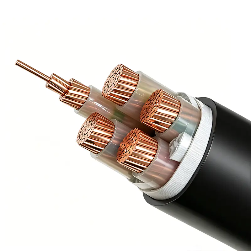
Rated Voltage 1.8/3kV XLPE Insulated Power Cable
9. Manufacturer Capability and Production Strength
Wuxi Guanghuan Cable Co., Ltd. is a China-based cable manufacturer founded in 1998 and headquartered in Guanlin Town, Yixing City, Jiangsu Province. The company operates in a region recognized for its strong cable manufacturing base and supplies products for power, industrial, energy, transportation, and specialized applications.
The company covers more than 100,000 square meters, including more than 45,000 square meters of building area. Its production and testing resources include more than 70 advanced lines, supported by technical personnel and experienced manufacturing teams.
This production scale is valuable for customers requiring stable supply, multiple specifications, repeat orders, and customized cable constructions. A broad manufacturing base can also support the coordination of conductor production, insulation extrusion, sheathing, armoring, testing, packaging, and technical service.
The company specializes in power cables, electrical equipment wires and cables, bare conductors, overhead insulated cables, high-speed railway and urban rail transit cables, energy storage cables, photovoltaic cables, and wind power cables. Its product portfolio includes more than 100 categories and over 30,000 specifications under the registered Liguang brand.
A broad product range demonstrates experience with different conductor materials, insulation systems, sheath compounds, voltage classes, flame-retardant designs, flexible structures, and industry-specific requirements. This experience can be useful when a customer requires more than a standard catalog cable.
The company reports certifications and management systems including ISO 9001 quality management, ISO 14001 environmental management, ISO 45001 occupational health and safety management, and ISO 50001 energy management. It also reports GB/T 29490 intellectual property management and additional systems relating to green management, social responsibility, and after-sales service.
These management systems help connect manufacturing quality with environmental responsibility, workplace safety, energy control, product development, and customer support. For large industrial projects, such systems can support supplier evaluation and documentation requirements.
Production quality is supported by equipment such as online eccentricity monitors, high-voltage series resonance testers, and partial discharge detectors. Online monitoring is particularly valuable during insulation extrusion because it enables prompt detection of thickness variation and improves process consistency.
The company also reports product and organizational recognition, including national high-tech enterprise status, specialized and innovative enterprise recognition, green factory recognition, intellectual property-related recognition, and quality integrity recognition. Its products have received or participated in certifications and evaluations such as CCC, TÜV, product carbon footprint, and China Energy-Saving and Environmentally Friendly Product certifications, according to the applicable product scope.
For power cables and conductors, the company has passed qualification and capability verification associated with the State Grid Corporation of China and serves power companies and major energy and engineering enterprises in China. Such experience can contribute to familiarity with formal technical specifications, inspection requirements, project documentation, and delivery coordination.
10. Product Advantages for Project Buyers
10.1 Higher Voltage Capability
The 1.8/3kV rating provides a stronger insulation level than ordinary 0.6/1kV cable. This makes the cable a better fit for industrial networks where the lower-rated cable would provide insufficient voltage margin or where higher system stability is required.
10.2 Stable Thermal Performance
XLPE insulation supports a 90°C continuous conductor temperature and a 250°C short-circuit temperature for a maximum of five seconds. These values provide a strong thermal basis for industrial power distribution when the cable is correctly sized and protected.
10.3 Broad Construction Choices
Copper and aluminum conductor options, armored and non-armored designs, steel tape or steel wire armor, and PVC or PE sheath options allow the cable to be adapted to different sites. Customers do not need to select a single construction for every application.
10.4 Reliable Electrical Testing
The 6.5kV AC withstand test and partial discharge control support confidence in insulation integrity. Combined with conductor resistance testing and dimensional inspection, these tests help verify that the cable is suitable for its intended operating conditions.
10.5 Suitability for Long Routes
For the same conductor cross-section and system conditions, a higher voltage system can transmit power with lower current than a lower-voltage system for the same power level. Lower current can reduce voltage drop and resistive losses. The actual result depends on the complete power system design, but the 1.8/3kV cable offers a useful option for longer industrial routes.
10.6 Manufacturing and Customization Support
A manufacturer with multiple production lines, extensive cable categories, advanced testing equipment, and technical personnel can provide greater support for customized conductor sizes, sheath materials, armor types, flame-retardant requirements, packing methods, and documentation.
11. Installation Recommendations
The minimum installation temperature is 0°C. If installation must take place below this temperature, preheating measures are required. Cold materials can become less flexible, increasing the risk of sheath cracking, insulation damage, or excessive bending stress during handling.
The minimum bending radius must not be less than 15 times the cable outer diameter. Installers should use the actual measured cable diameter or the manufacturer’s specified value when planning bends, terminations, trays, ducts, and pulling routes.
During pulling, the cable should not be dragged over sharp edges, abrasive surfaces, standing water, or contaminated ground. Pulling tension should remain within the permissible value for the selected construction. For armored cables, the armor and sheath must not be damaged by excessive pulling force or improper gripping equipment.
Cable rollers, guides, winches, cleats, and supports should be correctly positioned. In vertical installations, the cable must be supported so that its weight does not place excessive stress on terminations or intermediate connections.
For direct burial, the trench should be prepared to remove sharp stones and other objects that could damage the sheath. Backfill material should be suitable for cable installation, and warning tape or protective slabs may be used where required by local regulations and project specifications.
When cables are installed in parallel, adequate spacing should be considered. Closely grouped cables generate and retain more heat, which can reduce current-carrying capacity. Correction factors must be applied according to the number of circuits, installation arrangement, ambient temperature, and ventilation conditions.
In soil installations, the stated reference conditions are a soil temperature of 25°C, soil thermal resistivity of 2.0K·m/W, and direct burial depth of 0.7m. Actual conditions may differ substantially. Engineers should recalculate ampacity if soil thermal resistivity, moisture, burial depth, or cable spacing differs from the reference conditions.
For installation in air, the reference ambient temperature is 40°C, with a maximum long-term conductor temperature of 90°C. Higher ambient temperatures require correction, while lower ambient temperatures may permit a different permissible current after applying the relevant calculation method.
12. Selection Guidance
Before ordering the cable, the project engineer should confirm the system voltage, number of cores, conductor material, conductor cross-sectional area, installation method, route length, expected load current, short-circuit current, fault-clearing time, ambient conditions, and mechanical protection requirements.
Conductor size should not be selected solely according to normal load current. Voltage drop, short-circuit withstand, starting current, harmonic current, future load growth, installation grouping, and local regulations should also be considered.
Copper conductors may be preferred where compact dimensions, high conductivity, or connection convenience are priorities. Aluminum conductors may be attractive where reduced weight and lower material cost are important, particularly for large cross-sections and long cable routes. Terminations must be compatible with the selected conductor material.
Armored cable should be considered for direct burial, exposed industrial routes, tunnels, shafts, and areas with a significant risk of impact or compression. Non-armored cable may be suitable for protected installations where the cable is adequately enclosed, supported, and separated from mechanical hazards.
Steel tape armor is generally associated with compression and general mechanical protection. Steel wire armor is appropriate when higher tensile strength is required. The final choice should consider the cable route, installation method, vertical load, fault conditions, and applicable regulations.
PVC sheath is suitable for many general industrial applications. PE or specialized flame-retardant sheath materials may be selected for installations involving moisture, weather exposure, chemical conditions, or flame-propagation requirements.
Customers should also specify packaging, delivery length, drum dimensions, marking, inspection documents, test certificates, and any third-party witnessing requirements before production begins. Clear technical communication reduces the possibility of delays or mismatched construction.
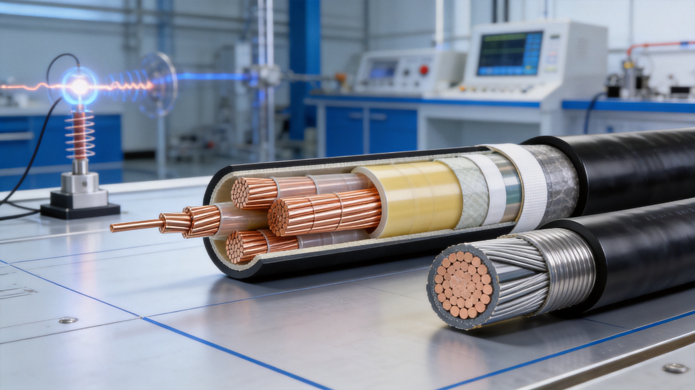
13. Inductance and Capacitance Reference Data
The following values provide reference inductance and capacitance data for selected specifications of the 1.8/3kV XLPE insulated power cable. Actual electrical parameters may vary according to cable construction, conductor arrangement, spacing, armor, sheath, and test conditions. Engineering calculations should use the approved product data for the specific ordered design.
Specification |
Inductance (mH/km) |
Capacitance (μF/km) |
4 |
0.3941 |
0.135 |
6 |
0.3686 |
0.154 |
10 |
0.3357 |
0.189 |
16 |
0.3137 |
0.222 |
25 |
0.2916 |
0.270 |
35 |
0.2787 |
0.308 |
50 |
0.2713 |
0.336 |
70 |
0.2600 |
0.389 |
95 |
0.2538 |
0.426 |
120 |
0.2474 |
0.473 |
150 |
0.2401 |
0.539 |
185 |
0.2374 |
0.569 |
240 |
0.2319 |
0.642 |
300 |
0.2278 |
0.709 |
400 |
0.2236 |
0.795 |
500 |
0.2208 |
0.865 |
14. Maintenance and Service Reliability
Although XLPE cables are designed for long-term service, proper maintenance remains important. Routine inspections should check cable supports, cleats, terminations, joints, sheath condition, grounding connections, and signs of overheating or mechanical damage.
Thermal imaging can help identify abnormal heating at terminals, joints, and cable connections. Excessive temperature may result from loose connections, overload, poor contact surfaces, unbalanced current, or insufficient ventilation.
Outdoor and direct-burial routes should be inspected for water accumulation, excavation activity, ground movement, exposed sheath, and damage caused by vehicles or construction work. In tunnels and industrial sites, inspection should also consider chemical exposure, vibration, fire protection, and cable support condition.
Electrical tests may be performed during commissioning, after significant repair, or as part of a planned maintenance program. Test methods and acceptance criteria should be selected according to the cable standard, system voltage, installation history, and recommendations from qualified electrical professionals.
Correct termination is essential. The termination must match the conductor material, insulation system, cable dimensions, voltage class, environmental conditions, and equipment interface. Poor stripping, contamination, inadequate stress control, or incorrect torque can compromise an otherwise high-quality cable.
15. Frequently Asked Questions
Q1: What does the 1.8/3kV rating mean?
The rating identifies the cable’s rated voltage between conductor and earth, U0, and between conductors, U. In this product, the rated voltage is 1.8/3kV. It is intended for power systems designed to operate at the applicable voltage level and should not be used outside its rated application without engineering approval.
Q2: Why is XLPE used instead of ordinary polyethylene?
Cross-linking changes the molecular structure of polyethylene and improves thermal stability, mechanical strength, and insulation performance. XLPE can support a 90°C maximum long-term conductor temperature and a 250°C maximum short-circuit conductor temperature for up to five seconds under the specified conditions.
Q3: Can this cable replace a 0.6/1kV cable?
It may be used instead of a lower-voltage cable when the system design, dimensions, terminations, installation method, and regulations permit. The 1.8/3kV cable provides a higher insulation level, but the final selection must consider conductor size, current capacity, cable diameter, cost, and equipment compatibility.
Q4: Is the cable suitable for direct burial?
Yes, an appropriately armored construction can be used for direct burial. The trench, bedding, backfill, burial depth, soil thermal resistivity, water conditions, and protection against excavation damage must be considered. The cable should be selected specifically for the actual site conditions.
Q5: What is the minimum bending radius?
The minimum allowable bending radius is not less than 15 times the cable outer diameter. The installation team should avoid sharp bends and use suitable rollers and guides to prevent damage during pulling and positioning.
Q6: What conductor materials are available?
The cable can be manufactured with copper or aluminum conductors. Copper offers high conductivity and compactness, while aluminum can reduce weight and may offer cost advantages for larger cross-sections. The termination system must be compatible with the selected material.
Q7: What is the difference between steel tape and steel wire armor?
Steel tape armor is generally selected for compression resistance and general mechanical protection. Steel wire armor provides greater tensile strength and may be preferred for vertical installations, shafts, or routes subject to pulling and longitudinal forces.
Q8: Can the cable be used in coal mines?
It can be manufactured for suitable mining applications when the required flame-retardant construction, certification, and industry standards are specified. Coal mine installations must comply with applicable safety regulations and product requirements, including relevant MT818 provisions where required.
Q9: What installation temperature is permitted?
The ambient temperature during installation should not be lower than 0°C. If installation occurs below 0°C, the cable should be preheated using an approved method to reduce the risk of cracking or mechanical damage.
Q10: How is current-carrying capacity determined?
Current-carrying capacity depends on conductor size, conductor material, installation in air or soil, ambient temperature, soil thermal resistivity, burial depth, cable spacing, grouping, and maximum conductor temperature. Reference tables and correction factors should be applied to the actual installation conditions.
Q11: Does a larger conductor always provide better performance?
A larger conductor generally reduces resistance and voltage drop, but selection must also consider cost, installation space, bending radius, termination compatibility, short-circuit requirements, and heat dissipation. The correct size is the result of a complete electrical and mechanical design.
Q12: What tests are performed on the cable?
Typical tests include conductor DC resistance, AC withstand voltage, insulation-related tests, partial discharge evaluation where applicable, dimensional inspection, sheath inspection, and other routine, sample, or type tests required by the applicable standard and purchase specification.
Q13: Can the cable be customized?
Construction details may be customized according to conductor material, core arrangement, cross-sectional area, armor, sheath, flame-retardant requirements, delivery length, marking, packaging, and applicable standards. The final design should be confirmed through a technical specification before production.
Q14: Which standards apply to the product?
The stated national standard is GB/T 12706.1, covering cables for rated voltages from 1kV with Um=1.2kV to 3kV with Um=3.6kV. Products may also be manufactured according to IEC standards or specific industry standards when requested and technically applicable.
Q15: Why is manufacturer testing capability important?
Testing capability helps verify conductor resistance, insulation integrity, partial discharge behavior, withstand voltage, dimensions, and sheath quality. Advanced equipment and controlled records provide stronger evidence that the manufactured cable meets the agreed technical requirements.
16. Conclusion
The rated voltage 1.8/3kV XLPE insulated power cable provides a reliable solution for industrial power transmission and distribution systems that require more insulation capability than ordinary 0.6/1kV cables. Its higher voltage rating, XLPE thermal performance, 90°C continuous conductor temperature, 250°C short-circuit temperature, and 6.5kV AC withstand test support dependable operation in demanding applications.
The product’s flexible construction options make it suitable for industrial distribution, large motors, variable-frequency equipment, mining, energy facilities, tunnels, cable trenches, shafts, direct burial, and other fixed installations. Copper or aluminum conductors, armored or non-armored structures, steel tape or steel wire armor, and PVC or PE sheaths can be selected according to project requirements.
Manufacturing quality is supported by controlled raw material management, conductor processing, precision insulation extrusion, cross-linking, online eccentricity monitoring, cable assembly, armoring, sheathing, high-voltage testing, partial discharge detection, and comprehensive inspection. These processes help reduce defects and provide consistent performance from production to installation.
With broad product experience, multiple production and testing lines, extensive specifications, technical personnel, management certifications, and experience serving power and engineering customers, Wuxi Guanghuan Cable Co., Ltd. can support both standard and customized cable requirements. The combination of product design, manufacturing capability, quality control, and technical service makes this 1.8/3kV cable a practical choice for reliable industrial power systems.
References
GB/T 12706.1, Cables for Rated Voltages from 1kV (Um=1.2kV) to 3kV (Um=3.6kV).
GB/T 3956, Conductors of Insulated Cables.
IEC 60502-1, Power Cables with Extruded Insulation and Their Accessories for Rated Voltages from 1kV to 3kV.
IEC 60228, Conductors of Insulated Cables.
MT 818, Coal Mine Cables and Related Technical Requirements, where applicable.
ISO 9001, Quality Management Systems—Requirements.
ISO 14001, Environmental Management Systems—Requirements with Guidance for Use.
ISO 45001, Occupational Health and Safety Management Systems—Requirements with Guidance for Use.
ISO 50001, Energy Management Systems—Requirements with Guidance for Use.
Manufacturer-provided technical data for rated voltage 1.8/3kV XLPE insulated power cable, including electrical parameters, operating conditions, structural options, and reference inductance and capacitance values.
Product: Rated Voltage 1.8/3kV XLPE Insulated Power Cable


Copyright © Wuxi Guanghuan Cable Co., Ltd. All Rights Reserved. Power Cables Manufacturer Electrical Wire And Cable Factory

