


 English
 中文简体
 русский
 Español
 عربى

Photovoltaic Cable: Reliable DC Power Transmission for Modern Solar Energy Systems
Content
- 1 The Role of Photovoltaic Cable in a Solar Power Plant
- 2 PV1-F and H1Z2Z2-K Cable Types
- 3 Compliance with Recognized Photovoltaic Cable Standards
- 4 Advanced Conductor Construction
- 5 Cross-Linked LSZH XLPO Insulation and Sheath
- 6 Resistance to Outdoor Environmental Conditions
- 7 Thermal and Electrical Performance
- 8 Current-Carrying Capacity
- 9 Temperature Conversion Factors
- 10 Flexibility and Installation Efficiency
- 11 Long-Term Service Life and Lifecycle Value
- 12 Applications in Different Solar Installations
- 13 Manufacturing Strengths and Quality Control
- 14 Advantages Compared with General-Purpose Cables
- 15 Installation and Engineering Considerations
- 16 Why Manufacturer Capability Matters
- 17 Frequently Asked Questions
- 17.1 What is a photovoltaic cable?
- 17.2 What is the difference between PV1-F and H1Z2Z2-K?
- 17.3 Why are PV cables made with tinned copper conductors?
- 17.4 What does LSZH XLPO mean?
- 17.5 Can ordinary electrical wire be used for solar panels?
- 17.6 What is the maximum conductor temperature?
- 17.7 What ambient temperature range is specified?
- 17.8 What is the minimum bending radius?
- 17.9 How long is the cable designed to last?
- 17.10 Where can these cables be used?
- 17.11 How should the cable size be selected?
- 17.12 Does the manufacturer provide large cable sizes?
- 17.13 Why is production testing important?
- 18 Conclusion
- 19 References
- 20 Product: Photovoltaic Cable (PV Cable)
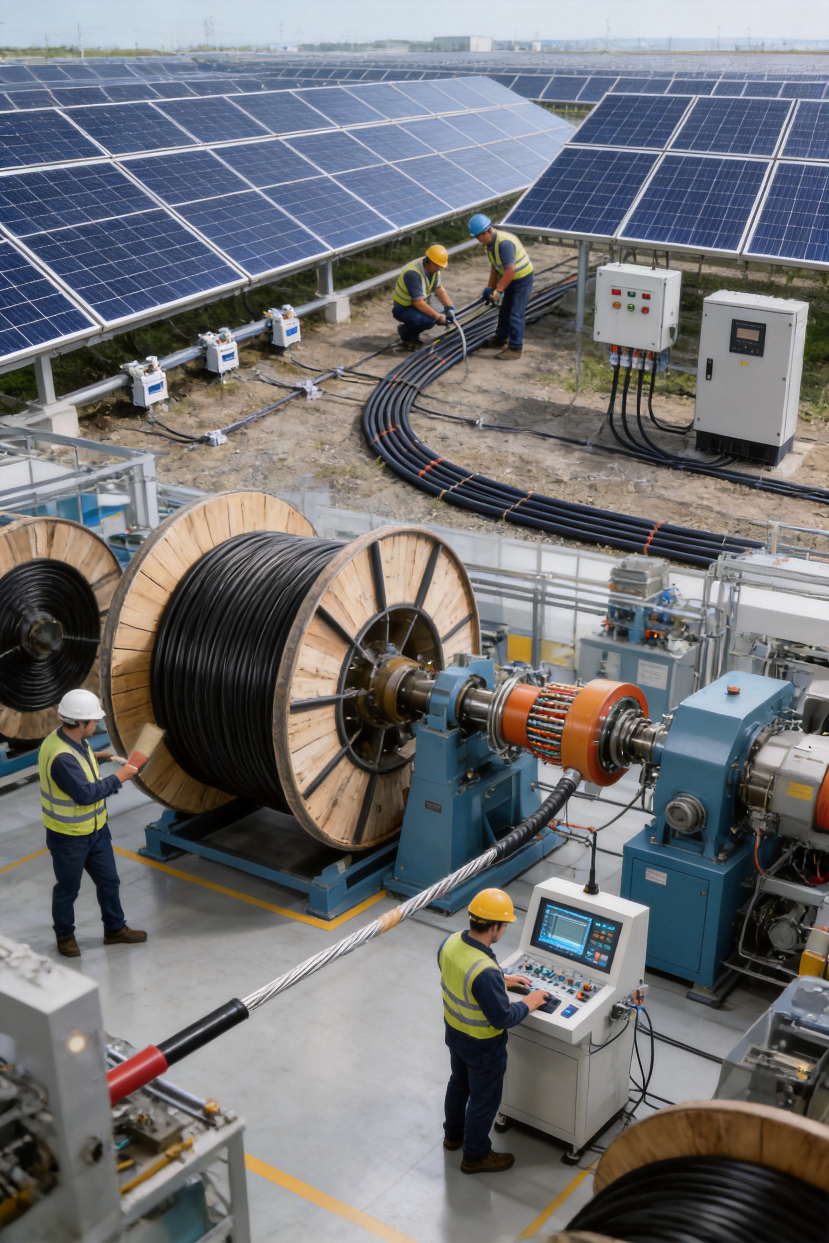
Photovoltaic cables are essential components in solar power generation systems. They transmit direct current electricity between photovoltaic modules, string connectors, combiner boxes, inverters, and other parts of the direct-current side of a solar installation. Although they may appear to be simple conductors, PV cables must perform reliably under continuous exposure to sunlight, temperature variation, moisture, wind, mechanical stress, chemicals, and demanding electrical conditions.
A cable designed for ordinary indoor electrical wiring is not automatically suitable for a photovoltaic installation. Solar cables require specialized insulation, sheath materials, conductor protection, flexibility, voltage capability, and resistance to environmental aging. The PV cable range described in this article is engineered for long-term outdoor service and is available in PV1-F and H1Z2Z2-K types. These cables use tinned copper conductors and cross-linked, low-smoke zero-halogen polyolefin insulation and sheath materials.
The product is intended to support safe, stable, and efficient electricity transmission throughout photovoltaic arrays. Its design combines compliance with recognized German and European standards, broad operating-temperature capability, strong resistance to weathering and ultraviolet radiation, excellent flexibility, and a service life designed to correspond with the long investment cycle of a solar power plant.
The Role of Photovoltaic Cable in a Solar Power Plant
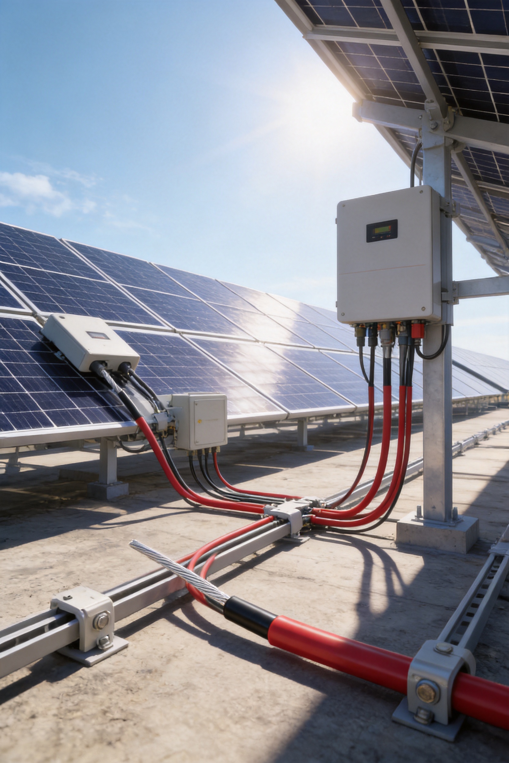
A photovoltaic power plant converts solar radiation into electrical energy through semiconductor modules. The modules generate direct current, which must be collected and transferred to an inverter. The inverter then converts direct current into alternating current for use by electrical loads or delivery to the grid. PV cables provide the electrical pathways that connect these components.
At the module level, short cable assemblies connect individual solar panels. These leads are commonly routed to adjacent modules or string connectors. At the string level, cables collect the output of several modules and carry it toward a combiner box or inverter. Larger cables may then be used for DC trunk lines between the array field and the inverter station.
These circuits are frequently installed outdoors, exposed to conditions that can accelerate cable deterioration. Cable surfaces may experience intense ultraviolet radiation, high temperatures, freezing conditions, rain, condensation, salt spray, dust, and chemical contamination. Cables may also be laid on mounting structures, suspended in the air, placed on ground surfaces, secured in cable trays, or installed in areas where repeated thermal expansion and contraction occur.
Because a photovoltaic system is expected to operate for many years, the cable must retain adequate insulation resistance, mechanical integrity, and current-carrying capability over a long period. A failure in a PV cable can reduce energy production, cause insulation faults, create maintenance costs, or introduce safety risks. Selecting a purpose-built solar cable is therefore an important part of photovoltaic system engineering.
PV1-F and H1Z2Z2-K Cable Types
The product range includes two important photovoltaic cable types: PV1-F and H1Z2Z2-K. Both are single-core solar cables intended for direct-current applications in photovoltaic systems. Their detailed ratings and size ranges differ, allowing engineers and installers to select an appropriate product for the required voltage, current, installation method, and project standard.
| Type | Primary application | Rated voltage information | Core configuration | Cross-sectional area | Applicable standard |
| PV1-F | Solar photovoltaic module and array connections | DC 1.8 kV; AC 0.6/1.0 kV | Single core | 1.5–35 mm² | 2PfG 1169/08.2007 |
| H1Z2Z2-K | Photovoltaic array and DC trunk-line applications | DC 1.5 kV; AC 1.0/1.0 kV | Single core | 1.5–240 mm² | EN 50618:2014 |
PV1-F is widely used for connections between photovoltaic modules, string circuits, and combiner equipment. Its available size range from 1.5 mm² to 35 mm² supports common module and string applications. H1Z2Z2-K extends the range to larger cross-sectional areas, reaching 240 mm², making it suitable for higher-current photovoltaic connections and larger DC transmission sections.
The selection between these cable types should be based on the electrical design, project specifications, applicable certification requirements, installation environment, and local regulations. System designers must also consider voltage drop, short-circuit current, ambient temperature, grouping, laying method, connector compatibility, and the required mechanical protection.
Compliance with Recognized Photovoltaic Cable Standards
Standards provide a common technical basis for cable design, material selection, testing, marking, and performance evaluation. The photovoltaic cable products described here are designed and manufactured in accordance with recognized German and European photovoltaic cable requirements.
2PfG 1169/08.2007
The PV1-F cable is specified according to 2PfG 1169/08.2007, a German TÜV standard for photovoltaic cables. This standard addresses the requirements associated with cables used in solar power systems, including their electrical, mechanical, thermal, and environmental performance.
EN 50618:2014
The H1Z2Z2-K cable is specified according to EN 50618:2014, a European standard covering electric cables for photovoltaic systems. Compliance with this standard supports the use of the cable in projects that require a recognized European technical basis for solar cable construction and performance.
Standards compliance is not simply a documentation exercise. It influences conductor construction, insulation and sheath properties, voltage testing, aging tests, dimensional control, and production verification. A manufacturer with an established quality system can integrate these requirements into material purchasing, process control, laboratory testing, and final inspection.
For international solar projects, standard-based manufacturing also simplifies technical evaluation. Engineering companies, EPC contractors, distributors, and system integrators can compare products using recognized specifications rather than relying only on general marketing descriptions.
Advanced Conductor Construction
The conductor is manufactured from high-purity electrical-grade tinned copper wire. Copper provides high electrical conductivity and low resistance, while tinning adds a protective layer to the copper surface.
Outdoor photovoltaic systems are frequently exposed to humidity and condensation. Bare copper can gradually oxidize when exposed to moisture and atmospheric contaminants. Oxidation can increase contact resistance and reduce the long-term reliability of terminals and connections. The tin layer helps limit oxidation and improves corrosion resistance in humid environments.
Tinned copper also offers practical advantages during cable termination. The surface supports reliable soldering performance and is compatible with many photovoltaic connectors and terminal systems designed for solar applications. When the cable is correctly crimped and installed using approved components, the conductor can provide a stable electrical connection for long-term service.
Conductor stranding is also important. A stranded conductor is more flexible than a solid conductor of the same cross-sectional area. This allows the cable to follow the shape of a module frame, mounting rail, cable management system, or equipment terminal without excessive mechanical stress. Flexibility is particularly useful during installation, maintenance, and the routing of cables between moving or closely spaced components.
Conductor size must be selected according to the expected current and installation conditions. A larger conductor can reduce voltage drop and power loss, but the final selection should also consider cost, bending space, connector capacity, thermal conditions, and short-circuit requirements. The available range up to 240 mm² gives system designers more options for higher-capacity DC circuits.
Cross-Linked LSZH XLPO Insulation and Sheath
The insulation and sheath layers use low-smoke zero-halogen cross-linked polyolefin, commonly described as LSZH XLPO. This material system is a major part of the cable’s performance in photovoltaic environments.
Cross-linking improves the thermal and mechanical stability of the polymer. Compared with materials intended primarily for ordinary indoor wiring, cross-linked polyolefin can offer better resistance to heat, deformation, environmental aging, and mechanical stress. These characteristics are important because solar cables may remain energized while exposed to elevated temperatures for long periods.
The low-smoke and zero-halogen characteristics provide additional safety benefits. If the cable is exposed to fire, the material is designed to produce minimal smoke and avoid the release of toxic halogen gases associated with halogen-containing compounds. This can help improve visibility and reduce corrosive or toxic emissions in the event of a fire, especially in equipment areas, buildings, tunnels, and other locations where people or sensitive electrical equipment may be present.
The insulation provides the dielectric barrier between the conductor and the external environment. It must maintain adequate electrical strength over the cable’s operating life. The sheath protects the cable from mechanical contact, moisture, sunlight, and environmental contaminants. Together, these layers form a cable structure designed for both electrical reliability and outdoor durability.
The use of an eco-friendly polyolefin material system also supports environmental objectives. The product is described as complying with RoHS environmental directives, which restrict the use of certain hazardous substances in electrical and electronic products. RoHS-oriented materials can help solar project developers meet environmental procurement requirements and support more responsible product selection.
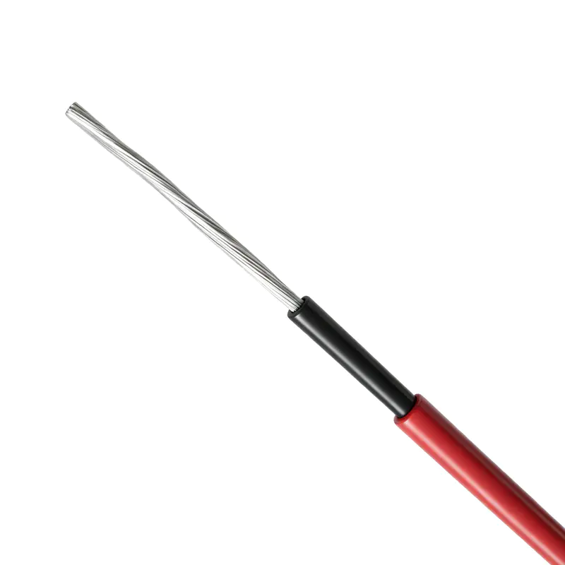
Photovoltaic Cable (PV Cable)
Resistance to Outdoor Environmental Conditions
Solar cables are often installed in locations where environmental exposure is more severe than in conventional electrical installations. A cable may be fixed below a module, routed along a metal support structure, placed in a cable tray, or installed in a solar field with little protection from the atmosphere. The product is developed to withstand several major outdoor stress factors.
Ultraviolet Radiation
Ultraviolet radiation can gradually degrade polymer materials. Prolonged exposure may cause cracking, embrittlement, discoloration, and loss of mechanical strength. Photovoltaic cable sheath materials are selected to resist this aging mechanism so that the external layer remains functional throughout long-term outdoor use.
Ozone
Ozone can affect certain rubber and polymer materials, particularly when the material is under mechanical tension. Resistance to ozone helps protect the cable sheath from surface cracking and premature deterioration. This is useful in areas with strong sunlight, high atmospheric activity, or equipment that experiences repeated thermal and mechanical movement.
Moisture and Humidity
Humidity, rain, condensation, and occasional water contact can affect cable materials and electrical connections. The tinned copper conductor helps resist oxidation, while the insulation and sheath provide an external barrier. Proper sealing, connector assembly, cable routing, and installation practices remain essential, but the cable’s material design provides an important first line of protection.
Acids, Alkalis, and Salt Spray
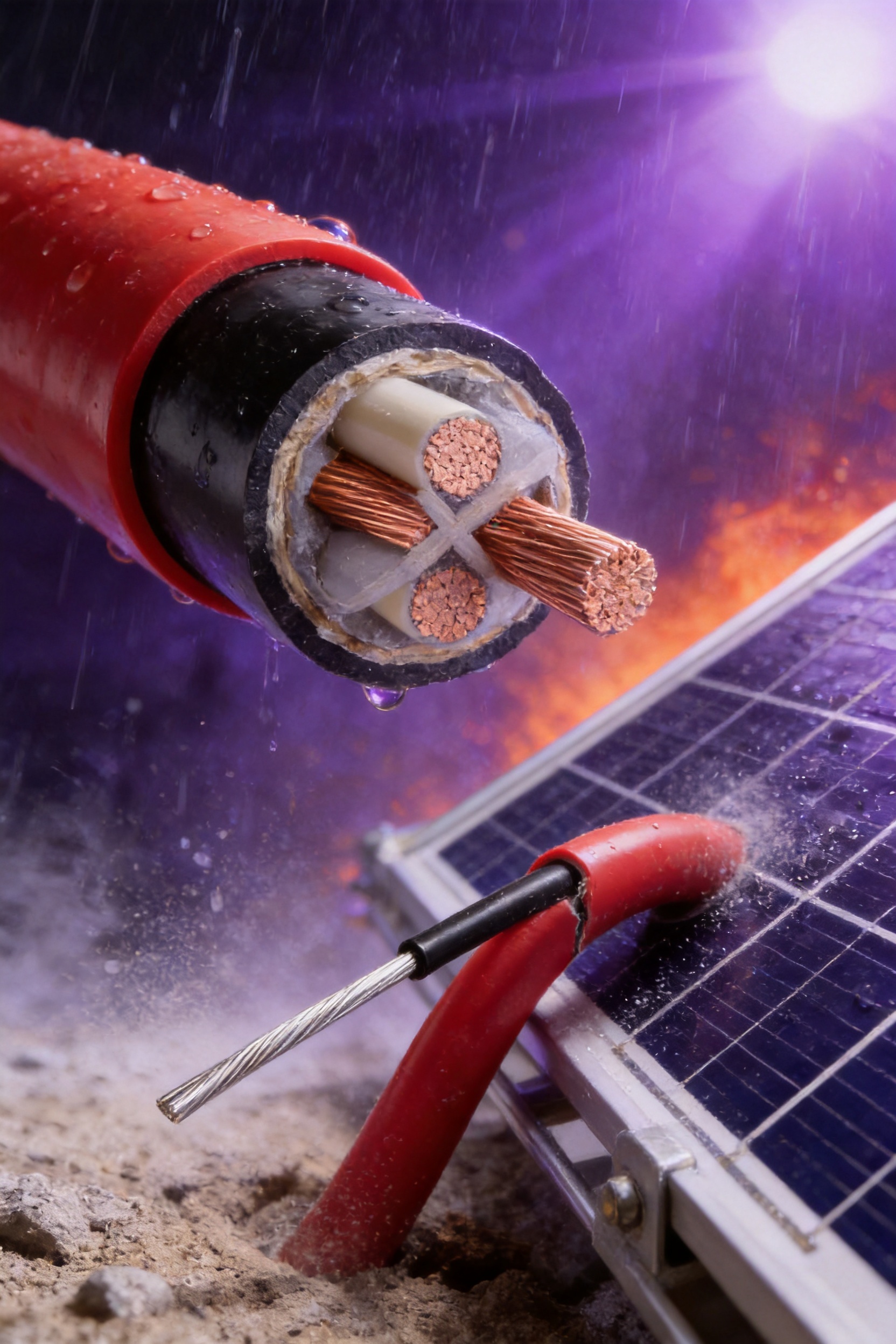
Photovoltaic installations may be located near coastlines, industrial areas, agricultural sites, deserts, or high-altitude regions. Salt spray, dust, acids, alkalis, and other contaminants can accelerate surface deterioration. The cable is intended to provide resistance to these environmental influences, making it suitable for a broad range of geographic conditions when installed according to the project requirements.
Temperature Fluctuation
Solar cables can experience substantial temperature changes between day and night and across different seasons. Dark mounting surfaces and direct solar radiation may raise the local cable temperature above the surrounding air temperature. The cable’s cross-linked insulation and sheath support stable performance across a specified ambient range from -40°C to +90°C.
Thermal and Electrical Performance
The cable is designed for operation in ambient temperatures from -40°C to +90°C. The maximum conductor operating temperature can reach 120°C under the specified conditions. In the event of a short circuit, the conductor can withstand a temperature rise to 200°C for up to five seconds.
| Performance parameter | Specified value |
| Ambient operating temperature | -40°C to +90°C |
| Maximum conductor operating temperature | 120°C |
| Maximum short-circuit conductor temperature | 200°C for up to 5 seconds |
| PV1-F rated voltage | DC 1.8 kV; AC 0.6/1.0 kV |
| H1Z2Z2-K rated voltage | DC 1.5 kV; AC 1.0/1.0 kV |
| Minimum bending radius | Not less than four times the cable outer diameter |
| Designed service life | Not less than 25 years |
Thermal performance directly affects current-carrying capacity. When a cable is installed in a hot environment, its ability to dissipate heat is reduced. The allowable current must therefore be adjusted using the appropriate temperature conversion factor. System designers should never apply a single current value without checking ambient temperature, installation method, conductor grouping, exposure to sunlight, and local electrical requirements.
The 120°C maximum conductor temperature is a design parameter, not an instruction to operate continuously at that temperature without engineering review. Continuous operation at elevated temperatures can influence cable life, connector performance, insulation aging, and the surrounding equipment. Correct sizing should balance electrical loading, thermal conditions, expected solar irradiance, and the required operating life.
The short-circuit temperature rating is relevant to the protection and coordination of photovoltaic circuits. If a fault occurs, the cable may experience a temporary high-current event before a protective device clears the fault. The stated short-circuit capability helps the cable tolerate this short-duration thermal stress within the specified time limit.
Current-Carrying Capacity
Current-carrying capacity depends on conductor cross-sectional area and installation conditions. A cable suspended in free air generally dissipates heat more effectively than a cable placed directly on a ground surface or installed close to other loaded cables. The following values represent the stated reference data for PV1-F cable at an ambient temperature of 60°C.
| Nominal cross-sectional area | Single-core cable in free air | Single-core cable on ground surface | Parallel cable on ground surface |
| 1.5 mm² | 30 A | 29 A | 24 A |
| 2.5 mm² | 40 A | 39 A | 33 A |
| 4 mm² | 55 A | 52 A | 44 A |
| 6 mm² | 70 A | 67 A | 57 A |
| 10 mm² | 98 A | 93 A | 79 A |
| 16 mm² | 132 A | 125 A | 107 A |
| 25 mm² | 176 A | 167 A | 142 A |
| 35 mm² | 218 A | 207 A | 176 A |
The reference values demonstrate why installation conditions matter. For example, a 10 mm² cable has a stated capacity of 98 A in free air, 93 A on the ground surface, and 79 A when installed in parallel on the ground surface. The reduction reflects the effect of heat accumulation and reduced cooling.
For larger H1Z2Z2-K cables, the stated current-carrying values extend to 240 mm². These values are provided for a 60°C ambient temperature and a maximum conductor temperature of 120°C.
| Nominal cross-sectional area | Single cable suspended in air | Single cable on surface | Two-load cable with two contacts on surface |
| 50 mm² | 276 A | 262 A | 221 A |
| 70 mm² | 347 A | 330 A | 278 A |
| 95 mm² | 416 A | 395 A | 333 A |
| 120 mm² | 488 A | 464 A | 390 A |
| 150 mm² | 566 A | 538 A | 453 A |
| 185 mm² | 644 A | 612 A | 515 A |
| 240 mm² | 775 A | 736 A | 620 A |
The values should be treated as technical reference data. Final cable selection must be verified against the applicable electrical code, project design, local ambient conditions, connector ratings, grouping factors, voltage-drop limits, and protection requirements.
Temperature Conversion Factors
When the ambient temperature rises above the reference condition, the allowable current should be reduced. The supplied PV1-F reference table gives the following conversion factors.
| Ambient temperature | Conversion factor |
| 60°C | 1.00 |
| 70°C | 0.91 |
| 80°C | 0.82 |
| 90°C | 0.71 |
| 100°C | 0.58 |
| 110°C | 0.41 |
A separate reference table for larger cable applications gives conversion factors of 1.00 at or below 60°C, 0.92 at 70°C, 0.84 at 80°C, and 0.75 at 90°C. The exact factor used in a project should correspond to the applicable cable type, table, installation method, and design standard.
Consider a cable with a reference capacity of 100 A at 60°C. If the applicable conversion factor at 80°C is 0.82, the adjusted capacity would be approximately 82 A before considering other derating factors. In a real design, additional corrections may be needed for cable grouping, conduit installation, burial, solar radiation, proximity to hot surfaces, and installation altitude.
The supplied technical information also notes an expected operating time limit of 20,000 hours at a maximum conductor temperature of 120°C and a highest ambient temperature of 90°C. This information should be interpreted together with the stated design service life and the actual operating profile of the solar project. Most installations do not operate continuously at the maximum thermal condition, and careful system design helps reduce thermal stress.
Flexibility and Installation Efficiency
Photovoltaic arrays often contain large numbers of modules arranged across mounting structures. Cable routes may need to pass around frames, support rails, junction boxes, connectors, and cable clips. A cable that is difficult to bend can increase installation time and place stress on terminals.
The product provides strong cold-bending and cold-winding performance. Its minimum bending radius is specified as not less than four times the cable outer diameter. This supports practical routing while preserving the integrity of the insulation and sheath.
Installers should still avoid sharp bends, twisting, crushing, excessive pulling force, and unsupported cable loops. A flexible cable is not immune to improper handling. The cable should be routed with suitable clips or supports, kept clear of sharp edges, and protected from movement caused by wind or thermal expansion.
Good cable management improves both installation quality and long-term maintenance. Cables should not be left in standing water, placed under excessive tension, or allowed to rub continuously against metal structures. Connectors should be fully engaged and should not be mismatched between different manufacturers unless compatibility has been verified.
Long-Term Service Life and Lifecycle Value
The product is designed for an expected service life of not less than 25 years. This target corresponds with the investment horizon of many photovoltaic power plants. Solar modules, mounting structures, inverters, and electrical cables are all expected to support reliable energy production over an extended period.
A long service life can reduce the risk of premature replacement and help lower maintenance costs. Cable replacement in a large solar field can be labor-intensive because cables may be routed beneath modules, along elevated structures, or through compact equipment areas. Preventing early cable deterioration is therefore more economical than relying on frequent corrective maintenance.
Lifecycle value depends on more than the initial purchase price. A cable with better resistance to ultraviolet radiation, temperature, moisture, ozone, and mechanical stress may provide a lower total cost of ownership when it reduces faults, inspections, downtime, and replacement work.
Reliable cable construction also protects the productivity of the entire system. A single damaged cable may disconnect a module string or cause an insulation fault. In a large plant, repeated small failures can accumulate into significant energy losses. The use of appropriately specified PV cables supports stable energy collection and predictable plant operation.
Applications in Different Solar Installations
Module-to-Module Connections
PV cables are used to connect the positive and negative leads of adjacent modules. These connections must be flexible, weather-resistant, and compatible with the module junction box and connector system. The cable should be routed so that it does not hang excessively, contact sharp edges, or become trapped between the module frame and mounting structure.
String Connections
Several modules connected in series form a string. The string cables carry the combined voltage of the modules while the current remains related to the module design and parallel-string arrangement. PV1-F cable sizes are commonly suitable for many string applications, subject to the project’s voltage, current, temperature, and voltage-drop calculations.
Combiner Box Connections
Combiner boxes collect multiple PV strings and provide switching, protection, monitoring, or surge protection functions. The cables entering and leaving the combiner box must be carefully identified and correctly terminated. Tinned copper conductors and robust insulation help support reliable connections in outdoor enclosures.
Array-to-Inverter DC Trunk Lines
DC trunk lines transmit collected power from the photovoltaic array to the inverter. These circuits may carry higher current and require larger cable sizes. H1Z2Z2-K cables with cross-sectional areas up to 240 mm² provide options for larger DC transmission requirements.
Rooftop Solar Systems
Rooftop systems expose cables to intense solar radiation and temperature changes. Space may also be limited, making flexibility and compact routing important. Low-smoke zero-halogen materials can provide additional benefits when cables are installed near occupied buildings or sensitive equipment.
Ground-Mounted Solar Farms
Ground-mounted projects may cover extensive areas and include long cable routes. Cables may be suspended from mounting structures, placed in cable trays, or routed near ground surfaces. Environmental resistance and suitable current-carrying capacity are important for these installations.
Coastal, Desert, and High-Altitude Projects
Coastal sites may expose cable surfaces to salt spray and high humidity. Desert sites may involve intense ultraviolet radiation, dust, large daily temperature changes, and limited shade. High-altitude sites may experience strong solar radiation and low ambient temperatures. The product’s resistance to ozone, ultraviolet radiation, acids, alkalis, and temperature variation supports use in diverse geographic environments.
Manufacturing Strengths and Quality Control
The manufacturer is an established cable enterprise founded in 1998 and located in Guanlin Town, Yixing City, Jiangsu Province, an area recognized for its cable manufacturing industry. Its production portfolio includes power cables, electrical equipment wires and cables, bare conductors, overhead insulated cables, high-speed railway and urban rail transit cables, energy-storage cables, photovoltaic cables, and wind-power cables.
The company operates more than 70 production and testing lines and employs technical professionals responsible for product development, process control, and quality assurance. Its manufacturing capabilities cover more than 100 product categories and over 30,000 specifications. This breadth indicates experience in managing different conductor designs, insulation systems, voltage levels, construction types, and customer requirements.
Advanced production equipment is used to control important cable parameters. Online eccentricity monitoring can identify uneven insulation thickness during extrusion. Eccentricity control is critical because a conductor that is not centered correctly can reduce insulation performance, affect outer dimensions, and create difficulties during termination or installation.
High-voltage series resonance testing equipment supports the verification of insulation withstand performance. Partial discharge detection equipment helps identify localized electrical defects or weak points in insulation systems. These technologies are valuable for cables used in high-reliability energy applications because they can reveal defects that may not be visible through ordinary visual inspection.
Manufacturing quality begins before extrusion. Conductor materials, polymer compounds, pigments, additives, and other components must be checked against purchasing specifications. During production, conductor stranding, tinning, insulation extrusion, cross-linking, sheath extrusion, cooling, take-up, and marking require process control.
After production, finished cables undergo dimensional, electrical, mechanical, and appearance inspections as required by the applicable product standard and customer specification. Consistent testing helps verify conductor resistance, insulation integrity, voltage withstand, outer diameter, flexibility, and other important properties.
The company maintains certifications including ISO 9001 quality management, ISO 14001 environmental management, ISO 45001 occupational health and safety management, and ISO 50001 energy management. It also holds certifications related to intellectual property, green management, social responsibility, and after-sales service. These systems support a more structured approach to manufacturing and customer support.
Product-related credentials listed for the company include CCC, TÜV, product carbon footprint, and China energy-saving and environmentally friendly product certifications. The specific certification applicable to a project should always be confirmed according to the selected cable type, size, production batch, and required market documentation.
Advantages Compared with General-Purpose Cables
Purpose-built PV cables offer several advantages over ordinary building wire or general-purpose power cable when used in solar installations.
Purpose-Built Environmental Protection
General-purpose indoor cables may not be designed for continuous ultraviolet exposure, ozone, outdoor moisture, or repeated temperature cycling. PV cables use materials selected for these conditions, helping reduce premature surface cracking and insulation deterioration.
Higher Solar-System Voltage Capability
Modern photovoltaic arrays can operate at elevated DC voltages. The stated PV1-F and H1Z2Z2-K voltage ratings support high-voltage DC applications, subject to the complete system design and applicable regulations.
Long-Term Thermal Performance
Solar cables may run hot because of direct solar radiation and proximity to module surfaces. Cross-linked insulation and sheath materials provide thermal stability appropriate for these conditions.
Improved Flexibility
Stranded tinned copper conductors and flexible polymer materials make the cable easier to route around module frames, mounting systems, and electrical equipment.
Reduced Smoke and Halogen-Free Construction
LSZH XLPO materials can reduce smoke generation and avoid toxic halogen gases during combustion. This can be particularly important for rooftop systems, commercial buildings, transport facilities, and enclosed electrical areas.
Broader Size Selection
The PV1-F and H1Z2Z2-K product range covers small module circuits and larger DC trunk lines. Sizes from 1.5 mm² to 240 mm² allow engineers to optimize current capacity and voltage drop for different plant configurations.
Long-Term Economic Benefits
A service-life design of at least 25 years can align the cable with the expected operating period of a solar plant. Durable materials and controlled production can help reduce replacement frequency, maintenance labor, and energy losses associated with cable faults.
Installation and Engineering Considerations
Correct installation is essential to achieve the cable’s specified performance. The cable should be selected according to the system’s maximum voltage, short-circuit current, expected operating temperature, installation route, and applicable code.
Voltage drop should be evaluated for both the positive and negative conductors over the full circuit length. Excessive voltage drop can reduce the energy delivered to the inverter and decrease overall system efficiency. Larger cross-sectional areas may be required for long cable runs even when the current is within the basic ampacity rating.
Thermal derating must account for cables bundled together, installed close to hot surfaces, laid on ground surfaces, placed in conduits, or exposed to intense solar radiation. Where multiple cables are installed in parallel, spacing and ventilation should be considered.
Connectors must match the cable size and conductor construction. Crimping tools should be suitable for the connector manufacturer’s specifications. Improper crimping can create high-resistance connections, local heating, and eventual failure. Connector housings should be fully engaged, and positive and negative terminals should be kept correctly separated.
Cable routes should avoid sharp metal edges and areas where water may collect. Suitable clips, ties, or supports should be used, but fastening devices should not crush the insulation. Cable loops should be arranged to avoid unnecessary movement in wind and should not rest directly on abrasive surfaces.
During storage and handling, cable drums should be protected from physical impact, excessive moisture, contamination, and prolonged unnecessary exposure to sunlight. Cable ends should remain sealed until installation. The cable should not be dragged across rough ground or bent below the specified minimum radius.
Before energization, the completed installation should be inspected and tested. Typical checks may include polarity, continuity, insulation resistance, connector condition, cable routing, labeling, and protective-device coordination. Testing should be carried out by qualified personnel using procedures appropriate to the system voltage and local requirements.
Why Manufacturer Capability Matters
Photovoltaic cable performance depends on the consistency of raw materials, extrusion conditions, conductor quality, cross-linking, dimensional control, and final testing. A manufacturer with broad cable experience can apply established process knowledge to solar cable production while maintaining specialized material and standard requirements.
Large-scale manufacturing capability can also support stable supply for utility-scale projects. Solar developers and EPC contractors may require substantial quantities across multiple sizes, colors, drum lengths, and delivery schedules. A manufacturer with multiple production and testing lines is better positioned to coordinate production capacity and quality verification.
Technical support is another important factor. Cable selection may involve current calculations, voltage-drop assessment, environmental considerations, connector compatibility, certification documents, and installation guidance. A supplier with technical personnel and a broad product portfolio can help customers evaluate options instead of treating the cable as an isolated commodity.
Quality management, environmental management, energy management, and after-sales systems provide an organizational framework for continuous improvement. These systems do not replace product testing, but they help establish repeatable procedures for purchasing, manufacturing, inspection, documentation, complaint handling, and corrective action.
Frequently Asked Questions
What is a photovoltaic cable?
A photovoltaic cable is a specialized electrical cable used primarily for direct-current connections in solar power generation systems. It connects modules, strings, combiner boxes, inverters, and other DC-side equipment. It is designed for outdoor exposure, elevated temperature, ultraviolet radiation, moisture, and long-term operation.
What is the difference between PV1-F and H1Z2Z2-K?
PV1-F and H1Z2Z2-K are different photovoltaic cable types with different applicable standards, voltage specifications, and size ranges. PV1-F is listed with sizes from 1.5 mm² to 35 mm² and compliance with 2PfG 1169/08.2007. H1Z2Z2-K is listed with sizes from 1.5 mm² to 240 mm² and compliance with EN 50618:2014. The correct choice depends on the project design and required standard.
Why are PV cables made with tinned copper conductors?
Tinning helps protect copper from oxidation in humid and outdoor environments. It can improve corrosion resistance and support soldering and termination performance. Tinned copper also retains the high conductivity and flexibility associated with copper conductors.
What does LSZH XLPO mean?
LSZH means low-smoke zero-halogen, while XLPO means cross-linked polyolefin. This material system is designed to provide thermal, electrical, and mechanical stability while producing limited smoke and avoiding toxic halogen gases during combustion.
Can ordinary electrical wire be used for solar panels?
Ordinary electrical wire should not be used in an outdoor PV application unless it has been specifically evaluated and approved for the required environmental, voltage, temperature, and mechanical conditions. Purpose-built PV cable is generally the safer and more reliable choice for solar DC circuits.
What is the maximum conductor temperature?
The specified maximum operating temperature of the conductor is 120°C. The cable is also stated to withstand a short-circuit conductor temperature of 200°C for up to five seconds. Actual system design must still apply the required ampacity and temperature derating rules.
What ambient temperature range is specified?
The stated ambient operating range is -40°C to +90°C. Current-carrying capacity must be adjusted when the installation temperature exceeds the applicable reference condition.
What is the minimum bending radius?
The specified minimum bending radius is not less than four times the cable outer diameter. The cable should not be bent sharply, twisted, crushed, or pulled excessively during installation.
How long is the cable designed to last?
The product is designed for an expected service life of not less than 25 years, corresponding to the long operating and investment cycle of many photovoltaic power plants. Actual service life depends on correct selection, installation, environmental exposure, loading, and maintenance.
Where can these cables be used?
Applications include connections between photovoltaic modules, string circuits, combiner boxes, inverters, and DC trunk lines. They may be used in rooftop systems, ground-mounted solar farms, and projects located in high-altitude, desert, coastal, or other demanding environments, subject to project requirements.
How should the cable size be selected?
Cable size should be selected based on maximum current, system voltage, circuit length, allowable voltage drop, ambient temperature, installation method, grouping, short-circuit conditions, connector ratings, and applicable electrical codes. A qualified electrical designer should complete the final selection.
Does the manufacturer provide large cable sizes?
The stated H1Z2Z2-K production range extends from 1.5 mm² to 240 mm². This provides options for both smaller photovoltaic circuits and larger DC trunk-line applications.
Why is production testing important?
Production testing helps verify conductor resistance, insulation integrity, voltage withstand, dimensional consistency, and other product characteristics. Equipment such as online eccentricity monitors, high-voltage resonance testers, and partial discharge detectors can support more reliable quality control.
Conclusion
Photovoltaic cables are fundamental to the safe and efficient operation of solar power systems. Their role extends beyond simple electricity transmission: they must preserve insulation integrity, control electrical losses, withstand outdoor exposure, tolerate thermal cycling, remain flexible during installation, and support the long service life expected from modern photovoltaic plants.
The PV1-F and H1Z2Z2-K cables described here combine tinned copper conductors with cross-linked LSZH XLPO insulation and sheaths. Their specified features include resistance to ultraviolet radiation, ozone, acids, alkalis, moisture, and temperature variation; operation across a broad ambient range; high voltage capability; short-circuit temperature tolerance; flexible installation; and an expected service life of at least 25 years.
The range also provides practical flexibility for project design. PV1-F cables cover common module and string applications, while H1Z2Z2-K cables extend to larger cross-sectional areas for higher-current DC circuits. Recognized German and European standards provide a technical foundation for product design and evaluation.
Manufacturing capability is equally important. The use of online process monitoring, high-voltage testing, partial discharge detection, multiple production lines, and integrated management systems supports consistent quality. Combined with technical experience across power, industrial, transportation, renewable-energy, and specialty cable applications, these strengths position the product range as a reliable solution for demanding solar projects.
For best results, cable selection and installation should always be completed according to the project’s electrical calculations, environmental conditions, applicable standards, and qualified engineering practices. When properly specified and installed, a purpose-built photovoltaic cable can help protect energy yield, reduce maintenance requirements, and support dependable solar power generation for decades.
References
2PfG 1169/08.2007, Requirements for Photovoltaic Cables.
EN 50618:2014, Electric Cables for Photovoltaic Systems.
RoHS Environmental Requirements for the Restriction of Hazardous Substances in Electrical and Electronic Equipment.
ISO 9001, Quality Management Systems Requirements.
ISO 14001, Environmental Management Systems Requirements with Guidance for Use.
ISO 45001, Occupational Health and Safety Management Systems Requirements.
ISO 50001, Energy Management Systems Requirements with Guidance for Use.
Photovoltaic Cable Product Standards and Technical Data Provided for PV1-F and H1Z2Z2-K Cable Products.
Technical Reference Tables for Photovoltaic Cable Ampacity, Temperature Conversion, and Installation Methods.
Product: Photovoltaic Cable (PV Cable)


Copyright © Wuxi Guanghuan Cable Co., Ltd. All Rights Reserved. Power Cables Manufacturer Electrical Wire And Cable Factory

