


 English
 中文简体
 русский
 Español
 عربى

Variable Frequency Drive Cable for Reliable High-Voltage Motor Control
Content
- 1 Why Variable Frequency Drive Cable Requires a Specialized Design
- 2 Product Overview
- 3 Core Technical Advantages
- 4 Comparison with Ordinary Power Cables
- 5 Product Structure and Cable Types
- 6 Rated Voltage and Production Range
- 7 Specified Technical Properties
- 8 Applications in Industrial Systems
- 9 Manufacturing Strength and Quality Control
- 10 How the Product Supports Total System Reliability
- 11 Installation Recommendations
- 12 Selection Guide for Engineers and Buyers
- 13 Advantages over Lower-Specification Alternatives
- 14 Maintenance and Inspection
- 15 Environmental and Operational Considerations
- 16 Company Capability and Customer Support
- 17 Frequently Asked Questions
- 17.1 What is a variable frequency drive cable?
- 17.2 How is a VFD cable different from an ordinary motor cable?
- 17.3 What cable types are included in this product family?
- 17.4 What rated voltages are available?
- 17.5 What is the maximum continuous conductor temperature?
- 17.6 What is the short-circuit conductor temperature?
- 17.7 What is the cable’s minimum bending radius?
- 17.8 Can the cable be installed in cold weather?
- 17.9 How effective is the screening system?
- 17.10 What is the partial-discharge requirement for the 3.6/6 kV cable?
- 17.11 Where can this cable be used?
- 17.12 How should the correct conductor size be selected?
- 17.13 Does the cable eliminate the need for an output filter?
- 17.14 Why is screen termination important?
- 17.15 What information should be included in an inquiry?
- 18 Conclusion
- 19 References
- 20 Product: Variable Frequency Drive Cable (Rated Voltage up to 6kV)
Modern industrial facilities depend on variable frequency drive systems to regulate motor speed, improve process control, reduce energy consumption, and support automated production. However, the performance of a variable frequency drive depends on more than the converter itself. The cable connecting the drive to the motor must also withstand rapid voltage pulses, high-frequency electrical stress, electromagnetic interference, thermal loading, and demanding installation conditions.
Variable Frequency Drive Cable, commonly called VFD cable or frequency converter cable, is engineered specifically for this environment. Unlike an ordinary power cable, it is designed to transmit power from a frequency converter to a motor while controlling the electrical effects created by pulse-width modulation. Its insulation system, screening structure, conductor arrangement, grounding configuration, and mechanical design work together to improve system stability and operational reliability.
The variable frequency drive cable described in this article is available in single-core and multi-core configurations, with rated-voltage options extending through medium-voltage applications. The product range includes main conductor cross-sections from 1.5 mm² to 400 mm² in applicable low-voltage designs, while larger voltage classes are available in selected conductor ranges. The cable is manufactured according to Q/320282 GAD016 and is intended for industrial automation, motor control, pump stations, substations, production lines, and other applications where high-frequency interference and voltage impulse resistance are important.
Why Variable Frequency Drive Cable Requires a Specialized Design
A conventional power cable is normally designed to carry sinusoidal alternating current at a relatively stable power frequency. A variable frequency drive produces a different electrical waveform. It rapidly switches semiconductor devices to create an adjustable-frequency output. The resulting voltage waveform contains steep rising and falling edges, high-frequency components, reflected-wave effects, and common-mode currents.
These electrical characteristics can create several risks if the cable is not properly designed. Fast voltage transitions may place additional stress on the motor insulation. High-frequency current may travel through unintended paths, including cable screens, protective conductors, bearings, grounding systems, and nearby metallic structures. Electromagnetic radiation can interfere with sensors, communication systems, programmable controllers, and measurement equipment. In addition, reflected waves may increase the voltage appearing at the motor terminals, particularly where long cable runs are used.
A specialized VFD cable addresses these problems through a combination of insulation performance and electromagnetic screening. The screening layer provides a controlled return path for high-frequency currents and reduces the emission of electromagnetic energy. A carefully configured protective or grounding conductor helps improve equipotential bonding and limits the voltage difference between the drive, cable, and motor. The result is a more predictable electrical environment for both the motor and the surrounding automation equipment.
The cable must also operate reliably under thermal and mechanical stress. Industrial cable routes may pass through cable trays, machine compartments, frequency-conversion cabinets, pump installations, and areas with frequent maintenance activity. A minimum bending radius of at least 15 times the cable outer diameter provides a practical safety margin during installation and helps protect the internal structure from excessive deformation.
Product Overview
The product is a screened power cable developed for frequency converter and variable frequency motor systems. It is suitable for power transmission or electrical connection between frequency converters rated at 10 kV and below, including 6 kV systems, and their associated motors. The design is particularly useful where high-frequency interference, motor noise, voltage impulse stress, and system reliability must be carefully controlled.
The cable family includes BPYJVP-type single-core and multi-core frequency-converter power cables. Depending on the application, the cable can be selected for different voltage levels, conductor sizes, neutral arrangements, and grounding requirements. This flexibility allows engineers to match the cable to the output current of the drive, the motor rating, the installation distance, and the local grounding architecture.
For the product range emphasized here, rated voltages include 0.6/1 kV, 1.8/3 kV, and 3.6/6 kV. The supplied production information also identifies additional voltage classes of 6/6(10) kV and 8.7/10(15) kV for the broader product family. Selection should always be based on the drive output, motor insulation system, installation environment, applicable electrical code, and the requirements of the project engineer.
The maximum continuous conductor operating temperature is 90°C. During a short circuit lasting no more than five seconds, the maximum conductor temperature can reach 250°C. These characteristics provide a useful balance between continuous current-carrying capability, overload tolerance, and insulation protection.
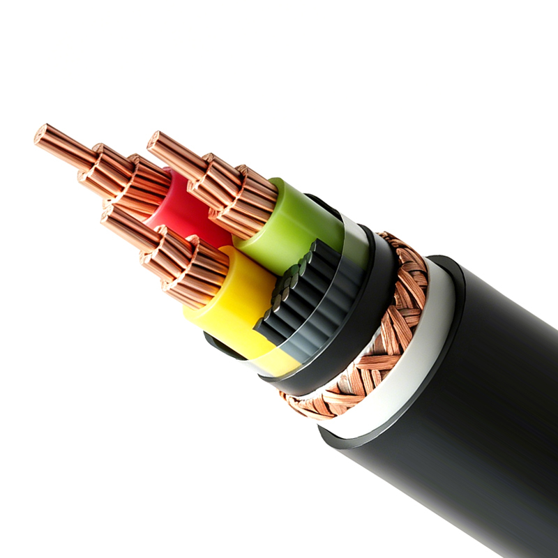
Variable Frequency Drive Cable (Rated Voltage up to 6kV)
Core Technical Advantages
High Voltage Impulse Resistance
One of the most important advantages of a VFD cable is its ability to tolerate repetitive voltage impulses. A frequency converter does not deliver a perfectly smooth sine wave. Instead, it creates a rapidly switched output whose voltage transitions can be much steeper than those found in a traditional motor supply.
The cable insulation system is designed to handle this electrical environment. Proper insulation thickness, material selection, conductor geometry, and manufacturing control help reduce the risk of localized electrical stress. This is especially important in medium-voltage applications, where even a small defect or irregularity in insulation can become a serious reliability concern.
For the 3.6/6 kV specification, the partial-discharge test at 1.73 U0 requires a discharge quantity of no more than 10 pC. This value indicates a stringent approach to insulation quality. Limiting partial discharge helps reduce the possibility of progressive insulation deterioration and supports long-term service performance under high-voltage operating conditions.
Effective Electromagnetic Screening
Electromagnetic compatibility is a major concern in variable frequency drive installations. The high-frequency switching action of the converter can generate conducted and radiated interference. If the cable does not provide an effective screening path, this interference may affect control circuits, instrumentation, industrial networks, safety systems, and nearby electronic equipment.
The product incorporates a high-performance screening structure. Its transfer impedance at 100 MHz is specified at no greater than 100 Ω/km. Transfer impedance is an important indicator of how effectively a screen limits the transfer of high-frequency voltage and current between the cable interior and its external environment. A lower value generally indicates better high-frequency screening performance.
This screening arrangement helps suppress electromagnetic interference and can reduce the operating noise associated with frequency-conversion motors. It also supports more stable signal transmission in industrial environments containing sensors, encoders, communication cables, programmable logic controllers, and other sensitive devices.
Screening performance depends not only on the cable itself but also on installation quality. The screen should be terminated correctly at the drive and motor ends according to the project grounding design. Poor termination, excessive pigtails, discontinuities, or improper bonding can reduce the benefit of a high-performance screen. For this reason, the cable’s technical advantages are most fully realized when the complete installation follows good EMC practice.
Optimized Conductor and Grounding Configuration
The main conductor cross-section range extends from 1.5 mm² to 400 mm² in the applicable production classes. This broad range allows the cable to serve small automated machines as well as large industrial motors, pumps, and power equipment.
Neutral or grounding conductors are available in selected cross-sections from 0.75 mm² to 150 mm², depending on the voltage class and technical design. The neutral and protective conductors can be configured according to the actual electrical requirements of the system. Other nominal cross-sections may also be designed and manufactured when justified by the application.
A properly sized grounding conductor is particularly important in a VFD system. High-frequency common-mode currents require a low-impedance path back to the drive. The grounding arrangement must support fault protection while also managing high-frequency current. A cable that combines phase conductors, protective conductors, and screening in a coordinated structure can provide more consistent performance than an improvised arrangement using separate ordinary cables.
Thermal Performance
The cable is rated for a maximum continuous conductor temperature of 90°C. This operating temperature supports demanding industrial duty cycles and provides a suitable thermal margin for many variable speed motor installations.
Thermal behavior depends on conductor size, installation method, ambient temperature, grouping, ventilation, and load profile. In a cable tray, several loaded cables may be installed together, reducing heat dissipation. In a cabinet or conduit, heat may accumulate differently. Engineers must therefore apply the appropriate ampacity correction factors rather than relying only on the nominal conductor area.
The short-circuit conductor temperature limit of 250°C for a maximum duration of five seconds provides additional protection during fault conditions. This rating is important for the coordination of cable size, protective devices, short-circuit current, and clearing time. The cable should always be used with a protection system capable of disconnecting faults within the specified thermal withstand period.
Mechanical Installation Reliability
Industrial installation routes are rarely perfectly straight. Cables may need to pass around drive cabinets, motor bases, cable trays, machinery, junction boxes, and structural supports. The recommended installation ambient temperature is not lower than 0°C. When the ambient temperature is above 0°C, construction can proceed directly without preheating, subject to normal handling precautions.
The minimum allowable bending radius is at least 15 times the cable outer diameter. Respecting this requirement helps prevent excessive stress on the conductor, insulation, screen, and sheath. Bending a cable too sharply can deform the screening layer, cause insulation damage, reduce mechanical strength, or create long-term electrical instability.
During installation, the cable should not be dragged over sharp edges or pulled beyond its permitted tensile load. Cable rollers, suitable pulling equipment, and correctly sized cleats should be used for larger cables. The cable should also be protected from crushing forces, repeated flexing, direct exposure to incompatible chemicals, and unnecessary torsion.
Comparison with Ordinary Power Cables
Ordinary power cables may be able to carry the fundamental current of a motor circuit, but they are not always optimized for the waveform generated by a variable frequency drive. The main difference is not simply voltage rating or conductor size. It is the way the cable manages high-frequency electrical behavior.
Performance area |
Ordinary power cable |
Specialized variable frequency drive cable |
Primary design objective |
General power transmission |
Power transmission under high-frequency switching conditions |
Voltage impulse management |
May not be optimized for repetitive steep-front pulses |
Designed to improve resistance to frequency-converter voltage impulses |
Electromagnetic compatibility |
Screening may be absent or limited |
High-performance screening structure with transfer impedance not greater than 100 Ω/km at 100 MHz |
Motor noise control |
Depends heavily on external installation measures |
Screening and grounding structure help reduce interference and motor operating noise |
Grounding arrangement |
May require separate protective conductor planning |
Neutral or grounding cores can be proportioned according to the technical design |
Medium-voltage suitability |
Must be individually assessed for converter output conditions |
Product family includes selected ratings through medium-voltage applications |
Industrial automation compatibility |
Potentially greater risk of interference in sensitive environments |
Designed to support stable operation near control and communication equipment |
The comparison does not mean that every conventional power cable is unsuitable for a drive system. Cable selection depends on the drive manufacturer, motor manufacturer, system voltage, cable length, switching frequency, grounding method, and installation environment. However, a purpose-designed VFD cable generally provides a more controlled and robust solution when high-frequency effects are important.
Product Structure and Cable Types
Single-Core Configuration
The single-core version is suitable for installations where phase conductors are arranged separately or where the system design requires large individual conductors. Single-core cables may be useful for high-current applications, large motors, power cabinets, and routes where cable spacing and magnetic field considerations can be carefully managed.
When installing single-core cables in alternating-current systems, the arrangement must be designed to limit induced currents and undesirable magnetic effects. Metallic supports, cable cleats, gland plates, and enclosure entries should be selected with the cable configuration in mind. The screening and grounding system must remain continuous and properly bonded.
Multi-Core Configuration
The multi-core version integrates the required conductors into one cable structure. This can simplify routing, improve phase symmetry, reduce installation time, and provide a more organized connection between the frequency converter and motor.
Multi-core cables are often practical for industrial equipment, automated lines, pump systems, and compact electrical rooms. They can help maintain a consistent relationship between phase conductors and associated grounding conductors, which is beneficial for electromagnetic performance.
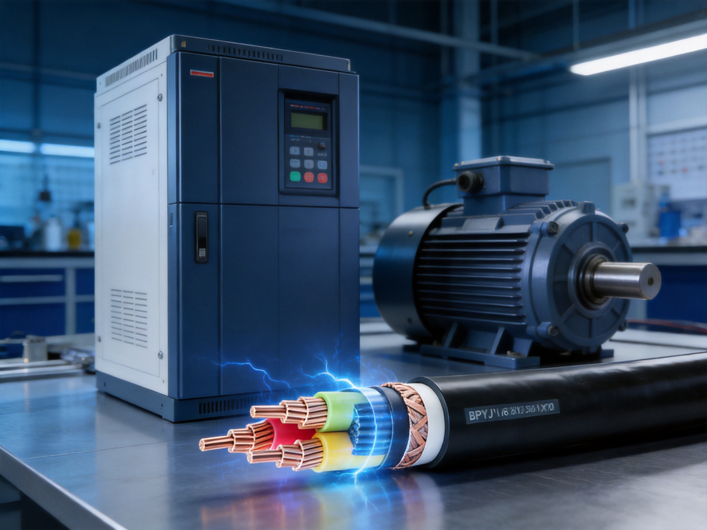
BPYJVP-Type Product Designation
The BPYJVP designation identifies the product family described in the supplied technical information. The product naming distinguishes single-core and multi-core frequency-converter power supply cables within the same general type series. Detailed ordering information should specify the number of cores, conductor cross-section, rated voltage, screening construction, sheath requirements, and any project-specific options.
Because different drive systems have different output currents and installation conditions, the cable should not be selected solely by its name. The complete technical description is needed to confirm voltage rating, current capacity, conductor material, grounding arrangement, screen design, and compliance requirements.
Rated Voltage and Production Range
The production range covers several rated-voltage categories. The following table summarizes the supplied conductor-size information.
Rated voltage |
Main-line core nominal cross-section |
Neutral or grounding core nominal cross-section |
Application note |
0.6/1 kV |
1.5–400 mm² |
0.75–150 mm² |
Suitable for a broad range of low-voltage variable frequency drive systems |
1.8/3 kV |
10–400 mm² |
According to technical design |
For higher-voltage motor control and power transmission requirements |
3.6/6 kV |
10–100 mm² |
According to technical design |
Medium-voltage specification with partial-discharge performance requirements |
6/6(10) kV |
16–400 mm² |
According to technical design |
Available in the broader product family where specified |
8.7/10(15) kV |
25–400 mm² |
According to technical design |
Available in the broader product family where specified |
The main product title emphasizes rated voltages up to 6 kV, while the supplied production table lists additional higher-voltage categories within the broader family. For procurement, the exact voltage designation should be confirmed with the manufacturer and matched with the drive output voltage and motor insulation system.
Specified Technical Properties
The cable is manufactured and tested with reference to Q/320282 GAD016. Conductor direct-current resistance is required to conform to GB/T 3956. This is important because conductor resistance affects voltage drop, power loss, heat generation, and motor performance.
For the 3.6/6 kV specification, the partial-discharge test at 1.73 U0 limits discharge to no more than 10 pC. The specified power-frequency voltage test values are 3.5 kV for 0.6/1 kV, 6.5 kV for 1.8/3 kV, and 11 kV for 3.6/6 kV. The four-hour power-frequency voltage test values are 2.4 kV, 7.2 kV, and 14.4 kV respectively.
The screening performance is specified by a transfer impedance value of no more than 100 Ω/km at 100 MHz for the listed voltage classes. This requirement is directly relevant to the cable’s ability to suppress high-frequency interference.
The thermal-extension test uses treatment conditions of 200 ± 3°C for 15 minutes, with mechanical stress of 20 N/cm². The maximum elongation during loading is 175%, and the permanent elongation after cooling is 15%. These values provide a way to evaluate the behavior of the insulation or polymeric material under controlled thermal stress.
Test or property |
0.6/1 kV |
1.8/3 kV |
3.6/6 kV |
Conductor DC resistance |
Conforms to GB/T 3956 |
Conforms to GB/T 3956 |
Conforms to GB/T 3956 |
Partial-discharge test at 1.73 U0 |
Not specified |
Not specified |
Not more than 10 pC |
Power-frequency voltage test |
3.5 kV |
6.5 kV |
11 kV |
Four-hour power-frequency voltage test |
2.4 kV |
7.2 kV |
14.4 kV |
Maximum transfer impedance at 100 MHz |
100 Ω/km |
100 Ω/km |
100 Ω/km |
Applications in Industrial Systems
Frequency Control Systems
The primary application is the connection between a frequency converter and its motor. The cable carries the converter’s variable-frequency output while helping control the electrical noise and common-mode current associated with switching operation.
Applications include conveyors, compressors, fans, mixers, extruders, machine tools, hoists, HVAC systems, water-treatment equipment, and process machinery. In each case, cable selection affects the motor’s insulation stress, electromagnetic compatibility, installation safety, and long-term maintenance requirements.
Automated Production Lines
Automated production lines often contain numerous drives, servo systems, sensors, communication networks, and control cabinets in a limited area. Electromagnetic interference from one drive can affect equipment several meters away if the cable system is poorly designed.
A screened VFD cable helps create a more controlled electrical environment. It can reduce the risk of interference with position sensors, temperature transmitters, encoders, industrial Ethernet systems, and safety circuits. This is particularly valuable where unplanned stops can cause production losses or quality problems.
Substations and Large Pump Stations
Pump stations and substations may use high-power motors operating under variable-speed control. These sites can contain long cable routes, high fault levels, multiple grounding points, and sensitive monitoring equipment. The available medium-voltage specifications and partial-discharge requirements make the product family suitable for projects requiring a more robust insulation system than a basic low-voltage cable.
Large pump stations also benefit from the cable’s thermal capability and flexible conductor-size range. Engineers can select a suitable cross-section according to motor current, route length, voltage drop, installation method, ambient temperature, and grouping conditions.
High-Precision Electrical Environments
Facilities with strict noise and interference requirements include semiconductor plants, precision manufacturing facilities, laboratories, data-related infrastructure, and advanced process-control installations. In these environments, a cable’s electromagnetic performance may be as important as its ampacity.
The screening structure and transfer-impedance requirement help support reliable operation where small electrical disturbances can affect measurements, control accuracy, or communication quality.
Manufacturing Strength and Quality Control
The manufacturer, Wuxi Guanghuan Cable Co., Ltd., was founded in 1998 and is based in Guanlin Town, Yixing City, Jiangsu Province, an area recognized as an important cable-manufacturing center in China. The company operates across more than 100,000 square meters, including over 45,000 square meters of building area.
Its manufacturing capabilities include more than 70 production and testing lines. The company employs more than 140 people, including over 30 technical professionals. This combination of production capacity and technical personnel supports the development of power cables, electrical equipment wires and cables, bare conductors, overhead insulated cables, railway and urban rail transit cables, and specialized cables for renewable energy and energy-storage applications.
The company reports annual sales revenue of approximately RMB 2 billion and annual output value exceeding RMB 3 billion. These figures indicate the capacity to support both standard production and larger project orders. A broad manufacturing base can also help maintain continuity of supply for customers requiring multiple cable categories or repeated deliveries.
The company offers more than 100 product categories and over 30,000 specifications under its registered Liguang brand. Although the VFD cable is a specialized product, it benefits from the organization’s broader experience in conductor processing, polymer insulation, cable screening, testing, product certification, and project service.
Advanced Production and Testing Equipment
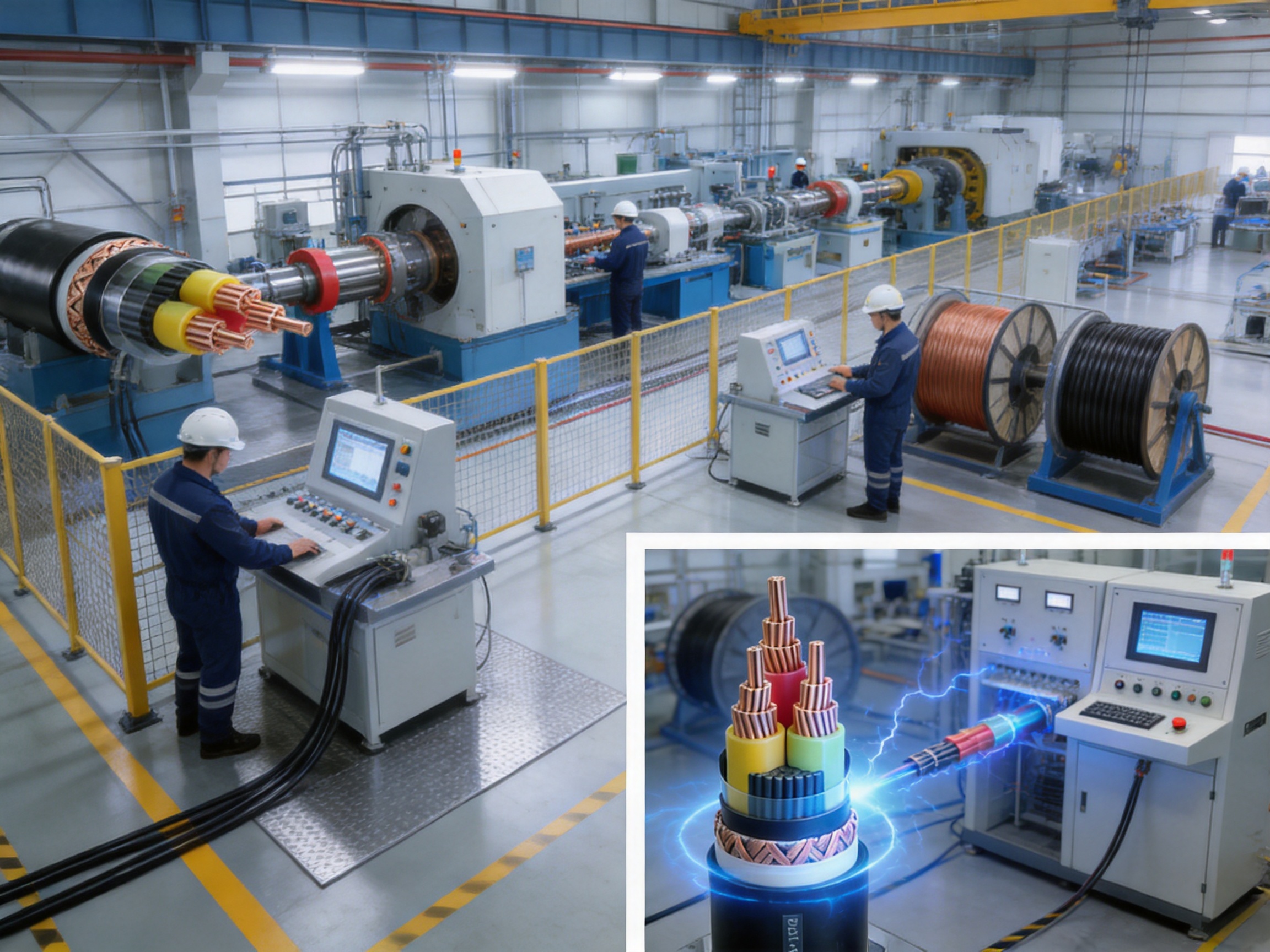
Manufacturing consistency is essential for high-performance cables. Small variations in conductor geometry, insulation thickness, eccentricity, screen coverage, or material processing can affect electrical performance. The manufacturer uses online eccentricity monitoring equipment to identify and control insulation uniformity during production.
High-voltage series-resonance testers support high-voltage withstand testing. Partial-discharge detectors support the inspection of medium-voltage insulation systems. These technologies are particularly relevant to 3.6/6 kV cables, where insulation defects may not be visible but can be detected through electrical testing.
Online process monitoring is valuable because it allows deviations to be identified during production rather than only after completion. Early detection can reduce material waste, improve manufacturing efficiency, and support more consistent product quality from one batch to another.
Management Systems and Certifications
The company has obtained ISO 9001 quality-management certification, ISO 14001 environmental-management certification, ISO 45001 occupational-health-and-safety certification, and ISO 50001 energy-management certification. It also reports certification related to intellectual property, green management, social responsibility, and after-sales service.
Product-related qualifications include CCC, TÜV, product carbon-footprint certification, and China energy-saving and environmentally friendly product recognition. The exact certification applicable to a specific cable model should be confirmed during technical and commercial evaluation.
These management systems provide a framework for controlling raw materials, production processes, testing, environmental impact, worker safety, documentation, and customer service. For industrial cable buyers, this type of structured management can be an important advantage over suppliers that provide only basic product data without a complete quality system.
Technical Development Capability
The company is recognized as a national high-tech enterprise and has been identified among China’s major machinery enterprises and specialized, sophisticated, distinctive, and innovative small and medium-sized enterprises in Jiangsu Province. It also reports recognition as a green factory, a national intellectual-property advantage enterprise, and a quality-integrity enterprise.
These qualifications reflect a focus on research, process improvement, product development, and controlled manufacturing. For VFD cable applications, technical development is especially important because the product must address multiple interacting requirements: voltage impulse resistance, insulation reliability, high-frequency screening, thermal performance, mechanical flexibility, and grounding compatibility.
How the Product Supports Total System Reliability
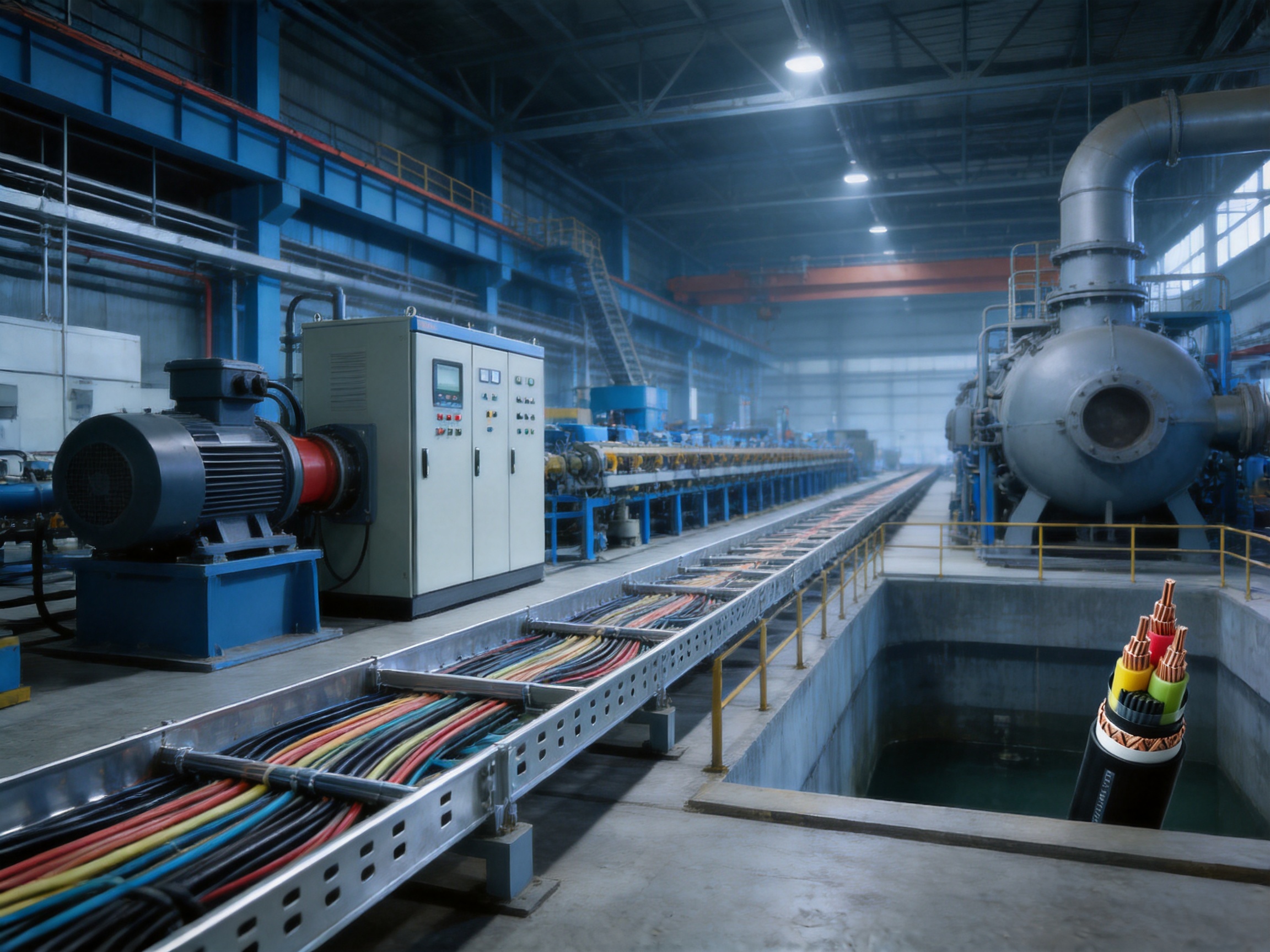
A drive cable is one part of a complete motor-control system, but its influence can extend across the entire installation. A well-designed cable can reduce the likelihood of nuisance tripping, communication errors, sensor instability, motor insulation damage, and excessive acoustic noise.
By reducing electromagnetic interference, the screened cable can help protect nearby control systems. By providing a controlled grounding and screening structure, it can help reduce common-mode current paths. By supporting medium-voltage insulation testing and partial-discharge control, it can improve confidence in high-voltage motor connections. By offering a wide range of conductor sizes, it can be matched more accurately to the load.
These benefits can reduce the need for corrective measures such as oversized external filters, improvised grounding straps, additional shielding conduits, or repeated troubleshooting of unexplained control faults. External filters and reactors may still be necessary in certain installations, but starting with a suitable cable provides a stronger foundation for the entire system.
Reliability also affects lifecycle cost. A lower initial cable price may not represent the lowest total cost if it leads to interference, early motor failure, difficult commissioning, or frequent maintenance. A purpose-designed VFD cable can contribute to more predictable commissioning and lower operational risk, especially in critical production facilities.
Installation Recommendations
Confirm Electrical Compatibility
Before ordering, confirm the drive output voltage, motor voltage, rated current, overload profile, switching frequency, cable length, and grounding system. The cable rating must be compatible with the actual output of the drive rather than only the incoming supply rating.
For medium-voltage systems, confirm the insulation coordination, partial-discharge requirements, termination design, and motor insulation capability. The cable, drive, motor, terminations, and protective devices should be evaluated as one system.
Plan Cable Routing
VFD cables should be routed separately from sensitive instrumentation, communication cables, and low-level signal wiring whenever possible. If power and signal cables must cross, a controlled crossing arrangement should be used. Parallel runs should be minimized where they may increase coupling.
The cable screen should remain continuous through junction boxes and equipment interfaces. Metallic cable trays, glands, and enclosures should be bonded according to the site grounding design. The installation should avoid unnecessary gaps or long unshielded sections between the cable and the motor terminals.
Respect Bending and Handling Requirements
The minimum bending radius is not less than 15 times the cable outer diameter. This requirement should be considered during route design, not only during final installation. Tight cabinet entries, sharp turns, and undersized gland plates can force the cable below its permitted radius.
Large cable drums should be lifted and unwound using suitable equipment. The cable should be protected against impact, crushing, water ingress, and contamination. Ends should remain sealed until termination to prevent moisture from entering the cable structure.
Terminate the Screen Correctly
The screen should be terminated using a method suitable for the frequency range and project EMC requirements. In many drive installations, a broad-area, low-impedance connection provides better high-frequency performance than a long thin pigtail. However, the final method must comply with the equipment manufacturer’s instructions and the site grounding design.
Incorrect screen termination can undermine the cable’s specified transfer impedance. It may also create unwanted circulating currents or increase electromagnetic emissions. Installation personnel should understand that the screen is not merely a passive protective layer; it is an active part of the high-frequency circuit.
Coordinate Protective Devices
The short-circuit withstand capability of the cable must be coordinated with fuses, circuit breakers, drive protection, and system fault-clearing time. A maximum conductor temperature of 250°C for up to five seconds does not authorize unrestricted fault duration. The protective system must interrupt the fault within the permitted thermal period.
Selection Guide for Engineers and Buyers
Several technical questions should be answered before selecting a VFD cable. First, what is the drive’s output voltage and maximum current? Second, what is the distance between the drive and motor? Third, is the motor low-voltage or medium-voltage? Fourth, are there sensitive control or communication systems nearby? Fifth, what are the ambient temperature, installation method, cable grouping, and mechanical conditions?
The conductor cross-section should be selected based on continuous current capacity, voltage drop, short-circuit performance, starting or acceleration conditions, and applicable derating factors. In a variable-speed application, the current waveform and harmonic content may also influence thermal design.
The cable configuration should be selected according to the number of phases, neutral requirements, protective-conductor requirements, installation space, and serviceability. Single-core cables may be preferred for certain high-current routes, while multi-core cables can simplify compact installations and improve phase organization.
For high-voltage applications, the design should include cable accessories. Terminations, stress-control components, glands, joints, and motor connection systems must be suitable for the cable’s voltage class and insulation construction. A high-quality cable cannot compensate for an unsuitable or poorly installed termination.
Buyers should request a technical datasheet, test report, conductor resistance data, insulation information, screening details, packing information, delivery requirements, and applicable certification. For customized projects, the order should clearly identify the voltage class, core arrangement, cross-section, cable length, sheath requirements, and testing requirements.
Advantages over Lower-Specification Alternatives
The product’s competitive advantages are based on its combination of electrical, mechanical, and manufacturing characteristics rather than on one isolated specification.
First, it is designed specifically for frequency-converter operation. This focus distinguishes it from general-purpose cables that may carry current adequately but provide less control over high-frequency effects.
Second, its screening design is supported by a defined transfer-impedance requirement of no more than 100 Ω/km at 100 MHz. A measurable EMC specification gives engineers a clearer basis for comparison than a generic statement that a cable is “shielded.”
Third, the product is available for both low-voltage and selected medium-voltage applications. The 3.6/6 kV product includes a partial-discharge requirement of no more than 10 pC at 1.73 U0, providing an additional level of insulation-quality verification.
Fourth, the conductor and grounding options are broad. Main conductors from 1.5 mm² to 400 mm² and selected grounding or neutral conductors from 0.75 mm² to 150 mm² allow more accurate system design than a narrow product range.
Fifth, the manufacturer combines large-scale production with specialized testing equipment, formal management systems, and technical personnel. This can support more consistent quality, stable supply, and customized production for demanding projects.
Finally, the product is supported by a company with experience across power transmission, electrical equipment cables, overhead conductors, rail-transit cables, photovoltaic cables, wind-power cables, and energy-storage cables. This broader expertise can be useful to customers seeking coordinated cable solutions for complete industrial or energy projects.
Maintenance and Inspection
Routine maintenance should include visual inspection of cable routes, terminations, glands, screens, supports, and protective devices. Technicians should look for signs of overheating, discoloration, mechanical damage, moisture, loose connections, and abnormal vibration.
Where the installation is critical, periodic electrical testing may be appropriate. The testing program should be established by qualified personnel and should consider the cable voltage class, service history, system design, and applicable standards. Medium-voltage systems may require specialized insulation and partial-discharge diagnostic techniques.
Unexpected motor noise, repeated drive trips, communication errors, encoder faults, or unexplained control instability may indicate an EMC or grounding problem. These symptoms do not automatically prove that the cable is defective, but the cable screen, termination, routing, and grounding should be inspected as part of the diagnosis.
Any repair or modification should preserve the cable’s electrical and mechanical design. Cutting away portions of the screen, extending the cable with an unsuitable joint, or replacing a termination with an incompatible component can significantly change system behavior.
Environmental and Operational Considerations
The cable is intended for industrial service, but environmental compatibility must still be assessed for every project. Relevant factors include ambient temperature, humidity, ultraviolet exposure, oil, chemicals, vibration, dust, water, rodents, mechanical impact, and fire requirements.
The 90°C continuous conductor rating provides a foundation for thermal design, but it does not eliminate the need for installation derating. Cables installed in enclosed spaces or grouped tightly together may operate at higher temperatures than cables installed in open, ventilated trays.
In areas with significant electromagnetic sensitivity, cable routing and bonding are especially important. The drive cabinet, cable screen, motor frame, protective conductor, and plant grounding system should be considered together. A coordinated design is more effective than relying on the cable alone.
For outdoor or underground applications, the sheath, water-blocking design, mechanical protection, and installation accessories should be confirmed. If the cable is exposed to direct sunlight, corrosive chemicals, or continuous movement, an appropriate product variation should be specified.
Company Capability and Customer Support
Wuxi Guanghuan Cable Co., Ltd. provides power cables, electrical equipment wires and cables, bare conductors, overhead insulated cables, high-speed railway and urban rail transit cables, and specialized cables for photovoltaic, wind-power, and energy-storage applications. This portfolio demonstrates experience in products requiring different combinations of electrical insulation, mechanical performance, environmental resistance, and regulatory compliance.
The company’s reported production scale, technical workforce, testing lines, and annual output capacity enable it to serve industrial customers, electrical contractors, system integrators, power companies, and major engineering enterprises. It has also passed qualification and capability verification for power cables and conductors conducted by the State Grid Corporation of China, according to the supplied company information.
For customers purchasing VFD cable, service quality is important because a cable order often involves technical confirmation rather than a simple commodity transaction. The supplier should help verify the cable type, voltage rating, conductor dimensions, screening structure, grounding cores, installation requirements, testing documents, packaging, and delivery schedule.
The company’s stated quality philosophy places quality first and customer needs at the center of production and service. Its reported after-sales service management system can support communication after delivery, including documentation, installation questions, product identification, and technical coordination.
Frequently Asked Questions
What is a variable frequency drive cable?
A variable frequency drive cable is a power cable specially designed to connect a frequency converter with a motor. It is built to manage the high-frequency voltage pulses, electromagnetic interference, common-mode currents, and grounding requirements associated with variable-speed drive systems.
How is a VFD cable different from an ordinary motor cable?
A VFD cable usually includes a more carefully engineered screening and grounding structure. It is designed for the fast switching waveform produced by a drive, not only for the transmission of conventional power-frequency current. This can improve electromagnetic compatibility and reduce stress on the motor insulation.
What cable types are included in this product family?
The supplied product information identifies BPYJVP-type single-core and multi-core power supply cables for frequency converters. The final selection depends on rated voltage, conductor cross-section, number of cores, neutral or grounding requirements, and installation conditions.
What rated voltages are available?
The highlighted product is rated up to 6 kV, with listed classes of 0.6/1 kV, 1.8/3 kV, and 3.6/6 kV. The broader production information also lists 6/6(10) kV and 8.7/10(15) kV categories. The exact voltage class must be confirmed for the specific project.
What is the maximum continuous conductor temperature?
The maximum continuous operating temperature of the conductor is 90°C.
What is the short-circuit conductor temperature?
The maximum conductor temperature during a short circuit can reach 250°C when the short-circuit duration does not exceed five seconds. Protective devices must clear faults within the applicable thermal withstand period.
What is the cable’s minimum bending radius?
The minimum allowable bending radius is not less than 15 times the cable outer diameter. This requirement should be respected during transportation, installation, termination, and maintenance.
Can the cable be installed in cold weather?
The recommended ambient temperature for installation is not lower than 0°C. When the temperature is above 0°C, installation can proceed directly without preheating, provided that normal handling and project procedures are followed.
How effective is the screening system?
The transfer impedance at 100 MHz is specified at no greater than 100 Ω/km. This provides a measurable indication of high-frequency screening performance. Correct screen termination and bonding are also essential to obtain the intended result.
What is the partial-discharge requirement for the 3.6/6 kV cable?
For the 3.6/6 kV specification, the partial-discharge test at 1.73 U0 requires a discharge quantity of no more than 10 pC.
Where can this cable be used?
Typical applications include frequency-control systems, automated production lines, substations, large pump stations, industrial machinery, process plants, and other environments requiring control of motor noise and high-frequency electromagnetic interference.
How should the correct conductor size be selected?
Conductor size should be selected according to motor current, drive output, voltage drop, cable length, installation method, ambient temperature, cable grouping, overload conditions, and short-circuit requirements. A qualified electrical engineer should confirm the final selection.
Does the cable eliminate the need for an output filter?
Not necessarily. A specialized VFD cable can reduce electromagnetic interference and improve system performance, but an output reactor, sine-wave filter, dv/dt filter, or other equipment may still be required depending on cable length, drive design, motor insulation, switching frequency, and project requirements.
Why is screen termination important?
The screen provides a path for high-frequency currents and helps contain electromagnetic energy. If it is terminated poorly or left discontinuous, the cable may not achieve its specified EMC performance, and interference may increase.
What information should be included in an inquiry?
An inquiry should identify the rated voltage, conductor cross-section, single-core or multi-core construction, number of cores, neutral or grounding conductor requirements, cable length, installation environment, applicable standards, testing documents, and delivery requirements.
Conclusion
Variable Frequency Drive Cable is an essential component for reliable industrial motor control. Its value lies in its specialized response to the electrical conditions created by frequency converters. High voltage impulse resistance, controlled electromagnetic screening, optimized conductor and grounding arrangements, 90°C continuous conductor operation, 250°C short-circuit performance, and a minimum bending radius of 15 times the outer diameter combine to support demanding applications.
The product’s transfer-impedance requirement of no more than 100 Ω/km at 100 MHz provides a clear technical basis for evaluating high-frequency screening. The 3.6/6 kV partial-discharge limit of no more than 10 pC at 1.73 U0 adds further confidence for medium-voltage applications. A broad range of conductor sizes and single-core or multi-core configurations supports flexible system design.
Manufacturing capability is another important strength. Wuxi Guanghuan Cable Co., Ltd. combines extensive production capacity, online eccentricity monitoring, high-voltage series-resonance testing, partial-discharge detection, formal management systems, and experience across many cable categories. These capabilities can help customers obtain stable product quality and coordinated technical support.
For the best result, the cable should be specified as part of a complete drive, motor, grounding, termination, protection, and routing system. When correctly selected and installed, it can reduce electromagnetic interference, improve motor-control stability, support high-voltage insulation reliability, and contribute to lower lifecycle risk in industrial electrical installations.
References
1. Q/320282 GAD016, Enterprise Technical Standard for Variable Frequency Drive and Frequency Converter Cables.
2. GB/T 3956, Conductors of Insulated Cables and Cords—Requirements for Electrical Resistance.
3. IEC 61800 Series, Adjustable Speed Electrical Power Drive Systems.
4. IEC 60502 Series, Power Cables with Extruded Insulation and Their Accessories.
5. IEC 60270, High-Voltage Test Techniques—Partial Discharge Measurements.
6. Product technical information supplied for BPYJVP-type variable frequency drive cables.
7. Manufacturer information supplied for Wuxi Guanghuan Cable Co., Ltd., including production capability, testing equipment, certifications, and product portfolio.
Product: Variable Frequency Drive Cable (Rated Voltage up to 6kV)

-
Variable Frequency Drive Cable (Rated Voltage up to 6kV)
-
Power Cable for Subway and Urban Rail Transit (Rated Voltage 35kV)
-
Cross-linked Polyolefin (XLPO) Insulated Wire and Cable (Rated Voltage 450/750V and below)
-
Flexible Fire-proof Cable (Rated Voltage 0.6/1kV)
-
Aerial Insulated Cable (Rated Voltage 1kV, 10kV, 20kV, 35kV)

Copyright © Wuxi Guanghuan Cable Co., Ltd. All Rights Reserved. Power Cables Manufacturer Electrical Wire And Cable Factory

