


 English
 中文简体
 русский
 Español
 عربى

35 kV Power Cable for Subway and Urban Rail Transit: Safety, Reliability, and Advanced Manufacturing
Content
- 1 1. The Role of 35 kV Cables in Urban Rail Transit
- 2 2. Main Product Construction and Model Options
- 3 3. Electrical and Thermal Performance
- 4 4. Fire Safety and Environmental Performance
- 5 5. Resistance to Termites, Rodents, and Environmental Stress
- 6 6. Bending Radius and Installation Requirements
- 7 7. Manufacturing Strengths and Quality-Control System
- 8 8. Advantages Compared with Conventional Cable Solutions
- 9 9. Application Scenarios
- 10 10. Selection and Project-Design Recommendations
- 11 11. Inspection, Testing, and Documentation
- 12 12. Frequently Asked Questions
- 12.1 What is the rated voltage of this cable?
- 12.2 Where is this cable mainly used?
- 12.3 What makes the cable suitable for subway environments?
- 12.4 What conductor sizes are available?
- 12.5 What is the maximum continuous conductor temperature?
- 12.6 What is the maximum short-circuit temperature?
- 12.7 Is the cable halogen-free?
- 12.8 Can the cable be supplied with flame-retardant performance?
- 12.9 What is the minimum bending radius?
- 12.10 Does the cable resist termites and rodents?
- 12.11 What testing supports the cable’s quality?
- 12.12 Can the manufacturer support customized project requirements?
- 13 Conclusion
- 14 References
- 15 Product: Power Cable for Subway and Urban Rail Transit (Rated Voltage 35kV)
Urban rail transit systems depend on a stable electrical infrastructure. Subways, light railways, and urban commuter lines operate in environments where electrical equipment must perform continuously, safely, and predictably. Power cables installed in tunnels, underground stations, trackside ducts, substations, and other restricted-access areas are especially important because a cable failure can interrupt transportation services, create serious maintenance challenges, and increase safety risks during an emergency.
The 35 kV power cable for subway and urban rail transit is designed for these demanding conditions. It is a specialized medium-voltage cable developed for power transmission in subway, light rail, and related urban rail systems. Its key features include low smoke, halogen-free or low-halogen construction, flame-retardant performance, resistance to termites and rodents, XLPE insulation, and a polyolefin-based or related protective sheath. Together, these features provide electrical reliability, fire-safety performance, and physical protection in complex underground and trackside environments.
The product is available for rated voltage levels of 21/35 kV and 26/35 kV. Conductor cross-sections are available up to 630 mm², allowing the cable to serve different current-carrying and power-distribution requirements. Depending on the installation design, users can select single-core or three-core constructions, as well as armored and unarmored versions.
Manufactured by Wuxi Guanghuan Cable Co., Ltd., the cable benefits from an established production system covering power cables, electrical equipment wires and cables, overhead conductors, railway cables, renewable-energy cables, and other specialized products. The manufacturer combines large-scale production capacity with testing facilities, process control, technical personnel, and certifications designed to support consistent product quality.
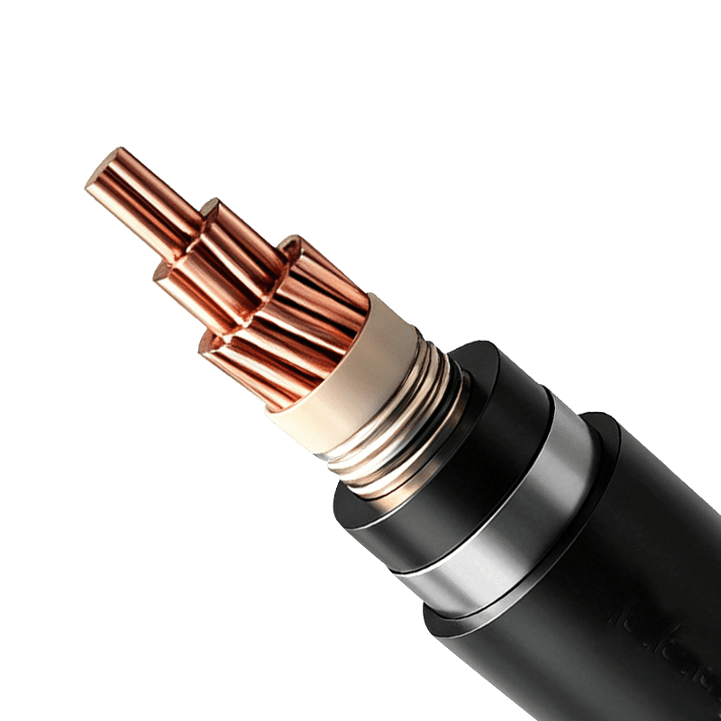
Power Cable for Subway and Urban Rail Transit (Rated Voltage 35kV)
1. The Role of 35 kV Cables in Urban Rail Transit
Urban rail systems require a dependable power network extending across stations, tunnels, depots, substations, ventilation facilities, signaling-support infrastructure, lighting systems, and auxiliary equipment. In many projects, a 35 kV distribution level is used to transmit electrical power efficiently over relatively long distances before it is transformed or distributed to lower-voltage equipment.
A cable used in this network must withstand electrical stress, mechanical handling, thermal cycling, moisture, dust, vibration, and the particular limitations of underground construction. It must also remain suitable for installation in locations where evacuation may be difficult and where smoke or corrosive gases could damage equipment or obstruct emergency response.
Traditional cable designs may provide adequate electrical transmission but may not fully address the combined requirements of modern rail infrastructure. For example, a conventional sheath may offer limited resistance to biological attack, while a cable containing halogenated materials may produce corrosive or opaque smoke during combustion. The 35 kV subway and urban rail transit cable responds to these concerns by integrating electrical insulation with fire-safety and environmental-protection characteristics.
Its intended application is therefore broader than ordinary power transmission. The cable is designed as part of a complete rail-transit safety system. Its construction helps protect the conductor and insulation during service, limits the consequences of fire, and reduces the probability of damage caused by termites and rodents along tunnels, cable trenches, outdoor sections, and trackside routes.
Suitability for Underground and Restricted-Ventilation Areas
Subway tunnels and underground platforms often have limited ventilation compared with open industrial sites. If a fire occurs, smoke can accumulate rapidly and affect passengers, workers, and emergency personnel. A low-smoke cable helps reduce the amount of visible smoke released during combustion, improving visibility and supporting evacuation and firefighting operations.
Halogen-free designs also help reduce the formation of corrosive acid gases. This is important because acidic combustion products can damage metal structures, electronic equipment, control cabinets, communication systems, and other infrastructure in addition to creating a direct health hazard.
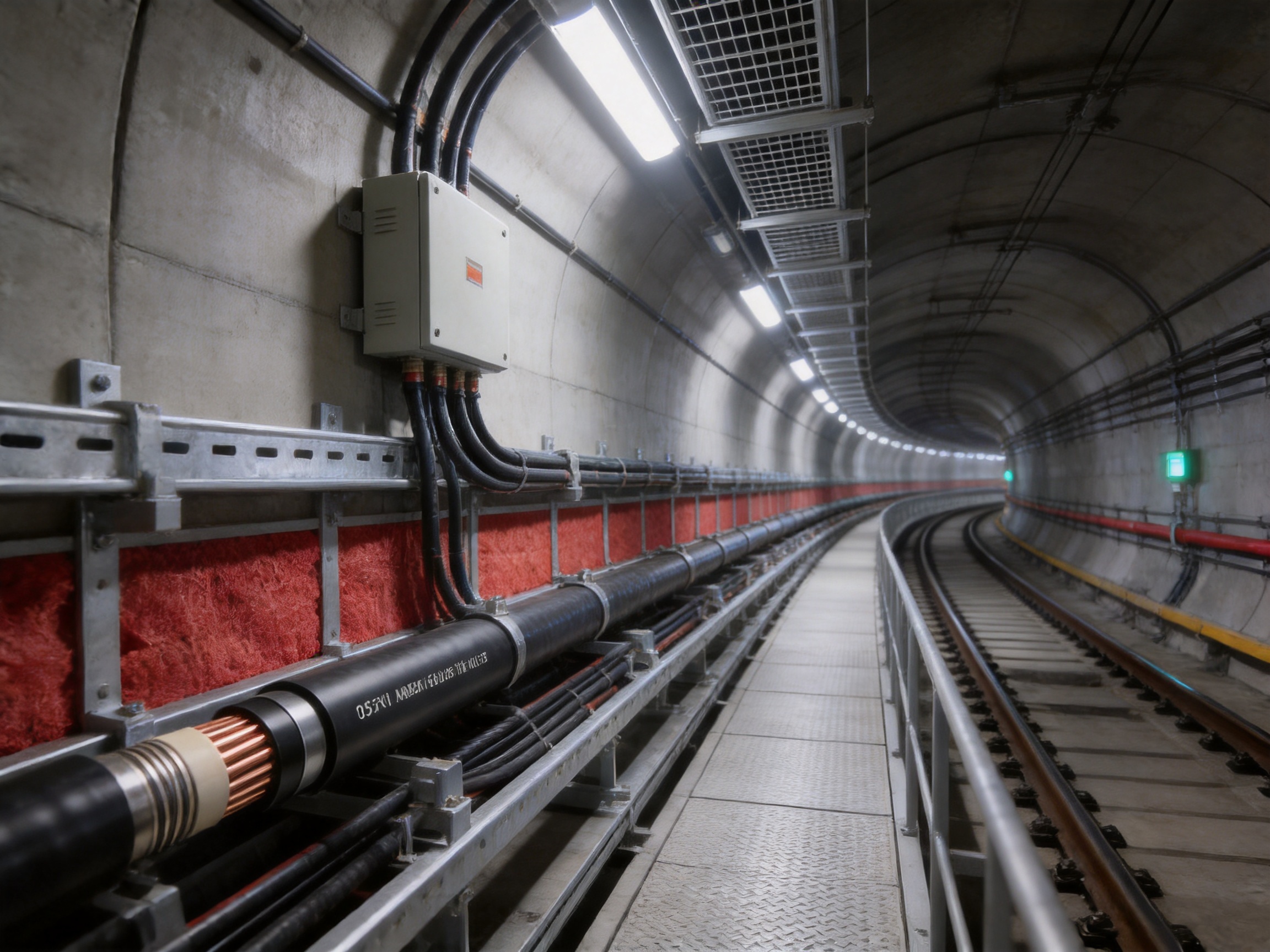
The cable is particularly suitable for tunnel power networks, underground platforms, station service systems, cable galleries, traction-related auxiliary networks, and other locations where fire performance and smoke control are important design considerations.
Protection Against Biological Damage
Termites and rodents can damage cable sheaths, insulation layers, and exposed sections of cable routes. Such damage may create leakage paths, reduce insulation reliability, expose metallic components to corrosion, or eventually cause a short circuit. Repair work can be disruptive in rail systems because access windows are often limited to scheduled maintenance periods.
The specialized sheath and protective material system used for this product is designed to resist termite and rodent damage. By reducing the likelihood of biological attack, the cable can provide a more durable power-transmission solution in areas with known pest activity, humid soil conditions, vegetation exposure, or trackside habitats.
2. Main Product Construction and Model Options
The cable combines a conductor, XLPE insulation, protective screen and other necessary layers, and an outer sheath selected for the intended environmental and fire-performance requirements. Depending on the model, the sheath and additives can provide low-smoke, halogen-free or low-halogen behavior, flame retardancy, ultraviolet resistance, and enhanced resistance to termites and rodents.
Conductor
The product uses copper conductors in the model examples supplied for this series. Copper provides high electrical conductivity, good connection performance, and reliable current transmission in medium-voltage distribution systems. Conductor direct-current resistance is controlled according to the relevant standard requirements.
The production range includes conductor cross-sections up to and including 630 mm². This range gives project designers flexibility when matching the cable to load demand, installation length, voltage-drop limitations, fault-current requirements, and available cable-routing space.
XLPE Insulation
Cross-linked polyethylene insulation is widely used in medium-voltage cables because it combines good dielectric strength with favorable thermal performance. In this product, the maximum continuous operating temperature of the conductor is 90°C. Under short-circuit conditions, the conductor temperature can reach a maximum of 250°C, subject to the specified short-circuit duration and applicable design conditions.
XLPE insulation also supports a relatively compact cable design compared with some older insulation systems. A compact design can simplify routing through tunnels, cable trays, ducts, and station service areas while maintaining the required electrical performance.
Protective Sheath
The outer sheath is one of the most important distinguishing features of the product. It provides a physical barrier against abrasion, environmental stress, moisture, and biological attack. The sheath material is designed to resist environmental stress cracking, a failure mechanism that can occur when a polymer is exposed to mechanical stress and environmental influences over a long period.
The sheath system also supports the product’s fire and smoke performance. In the halogen-free version, combustion produces limited acid gas and the smoke is designed to retain a light transmittance of not less than 60 percent under the stated test conditions. The low-halogen option has a stated light transmittance of not less than 30 percent and different acid-gas performance requirements.
Armored and Unarmored Versions
Unarmored cables may be selected where the cable is installed in protected ducts, trays, galleries, or other controlled routes. Armored cables can provide additional mechanical protection in locations where the cable may be exposed to impact, pressure, pulling forces, or other external stresses.
The choice between armored and unarmored construction should be based on the project’s cable-routing design, installation method, mechanical-risk assessment, earthing arrangement, electromagnetic requirements, and local engineering specifications. The cable manufacturer can provide the appropriate construction and technical data for the intended installation.
Representative Product Models
One representative model is (FZ-FSY)-WD-TYJY. This type is described as a copper-conductor, XLPE-insulated, polyolefin-sheathed power cable for subway and light-weight track applications, with low-smoke, non-halogen, ultraviolet-protection, termite-resistant, and rodent-resistant characteristics.
Another representative model is (FZ-FSY)-DD-TYJV. This type is described as a copper-conductor, XLPE-insulated, polyolefin-sheathed low-halogen and low-smoke power cable for subway and lightweight-track applications, with ultraviolet, termite, and rodent protection.
Flame-retardant grades identified as ZA, ZB, or ZC may also be supplied according to project requirements. The final model should be selected according to the fire classification, cable arrangement, installation environment, electrical design, and applicable procurement specification.
| Item | Product Information | Project Significance |
|---|---|---|
| Application | Subways, light railways, urban commuter railways, tunnels, and trackside power systems | Supports reliable medium-voltage power distribution in rail infrastructure |
| Rated voltage | 21/35 kV and 26/35 kV | Suitable for specified 35 kV-class distribution networks |
| Insulation | Cross-linked polyethylene | Provides stable dielectric and thermal performance |
| Conductor | Copper, with cross-sections up to 630 mm² | Supports different load levels and project configurations |
| Maximum continuous conductor temperature | 90°C | Supports continuous operation under the specified thermal conditions |
| Maximum short-circuit conductor temperature | 250°C under the stated short-circuit condition | Provides thermal capability during fault events |
| Fire and smoke options | Low-smoke, halogen-free or low-halogen, flame-retardant options | Helps reduce smoke, corrosive gas, and fire-spread risks |
| Biological protection | Termite- and rodent-resistant construction | Reduces the risk of sheath and insulation damage |
| Maximum production cross-section | 630 mm² and below | Offers selection flexibility for different rail loads |
3. Electrical and Thermal Performance
Medium-voltage cable reliability depends on the interaction of conductor resistance, insulation quality, electric-field control, thermal behavior, and manufacturing consistency. The 35 kV rail-transit cable is designed to maintain stable performance under normal operation while also tolerating specified electrical and thermal stresses.
Rated Voltage
The stated rated voltage levels are U0/U 21/35 kV and 26/35 kV. In this designation, U0 represents the rated power-frequency voltage between the conductor and earth, while U represents the rated voltage between conductors. The correct voltage class must be matched to the system design and the operating characteristics of the rail network.
Project engineers should confirm the system earthing arrangement, insulation coordination, switching conditions, fault levels, and applicable national or enterprise requirements before selecting the final cable specification.
Continuous Operating Temperature
The permissible maximum continuous operating temperature of the conductor is 90°C. This value is important for calculating the cable’s current-carrying capacity. Actual ampacity depends on conductor size, installation method, spacing, ambient temperature, soil thermal resistivity, grouping, ventilation, shielding, and other conditions.
A cable should not be rated solely according to its conductor cross-section. For a rail project, the designer should evaluate the complete installation system. Cables installed together in a tunnel or duct may experience mutual heating, while cables installed in a ventilated tray may dissipate heat more effectively. Manufacturer data and project-specific calculations should be used to establish the permitted operating current.
Short-Circuit Performance
The cable is designed for a maximum conductor temperature of 250°C during a short circuit under the specified short-circuit duration. The supplied technical information includes different duration references in separate descriptions. Consequently, the final project specification should confirm the exact short-circuit duration and calculation basis with the manufacturer and the approving engineer.
Short-circuit performance is affected by the conductor material, cross-sectional area, initial operating temperature, protective-device clearing time, screen or metallic-layer design, and the thermal properties of surrounding materials. Proper coordination between the cable and the protection system is essential.
Voltage Resistance Testing
The product is required to pass a 3.5 U0 alternating-current and direct-current voltage resistance test according to the stated technical requirements. This test places significant electrical stress on the insulation system and helps verify the integrity of the cable’s dielectric structure.
High-voltage testing is only one part of quality assurance. Reliable medium-voltage cable production also depends on clean materials, accurate extrusion, stable dimensions, concentric insulation, proper screening, controlled cross-linking, and effective testing for partial discharge and other defects.
4. Fire Safety and Environmental Performance
Fire performance is a central consideration in subway and urban rail projects. A cable installed in a tunnel or station should not become an uncontrolled source of flame propagation, dense smoke, or corrosive gas. The specialized construction of this product is intended to address these risks through low-smoke materials, halogen-free or low-halogen options, and flame-retardant grades.
Low-Smoke Behavior
Smoke can reduce visibility, interfere with evacuation, and complicate the work of emergency responders. The halogen-free cable is specified to achieve a light transmittance of not less than 60 percent during combustion under the applicable test method. The low-halogen cable has a stated light-transmittance requirement of not less than 30 percent.
These values provide an objective basis for evaluating smoke performance. In an underground rail environment, higher light transmittance can contribute to better visibility compared with cable materials that generate heavy, opaque smoke.
Halogen-Free and Low-Halogen Options
Halogen-free cable materials are designed to limit the release of halogen acid gases during combustion. For the non-halogen product, the total acid-gas emission is stated as no higher than 5 mg/g. The pH value of escaping gas is not less than 4.3, and conductivity is no higher than 10 μS/mm.
These indicators are important because the chemical properties of smoke can affect both people and equipment. Acidic and conductive gases may corrode metal components, printed circuit boards, contacts, control units, communication equipment, and signaling-related systems.
For projects that require a low-halogen rather than a halogen-free solution, the relevant model can be selected. The supplied specifications identify a different light-transmittance and acid-gas performance level for low-halogen cable. The project’s fire-safety specification should determine which construction is appropriate.
Flame Retardancy
ZA, ZB, and ZC flame-retardant cable grades may be supplied according to request. Flame retardancy helps limit the spread of fire along a cable route. This is especially useful where several cables are installed together in trays, shafts, ducts, or tunnels.
Flame-retardant performance should be evaluated together with cable spacing, route compartmentalization, fire barriers, support systems, penetration seals, ventilation, and emergency procedures. No cable can replace a complete fire-protection design, but the correct cable construction can significantly reduce the potential for fire propagation and secondary damage.
5. Resistance to Termites, Rodents, and Environmental Stress
One of the product’s most important advantages over ordinary power cables is its integrated biological-protection design. Termites and rodents can be found in soil, vegetation zones, cable trenches, station surroundings, and trackside environments. Their activity can create small defects that gradually develop into serious electrical failures.
Termite Resistance
Termite-resistant cable sheaths are formulated and processed to discourage termite attack and reduce the likelihood that insects will penetrate the protective layers. This is valuable for underground sections, outdoor transition areas, depots, and routes passing through regions with a known termite population.
Termite resistance can reduce the need for frequent inspection and replacement, particularly where cable access is difficult. It also helps protect the insulation system from damage that may not be immediately visible during routine maintenance.
Rodent Resistance
Rodents may gnaw cable sheaths because of their natural behavior, nesting activity, or access to cable trenches and equipment rooms. A damaged sheath exposes the cable to moisture, mechanical stress, and contamination. In severe cases, rodents may damage insulation or metallic layers as well.
The specified rodent-resistant construction creates a stronger protective barrier than a standard sheath. This can be especially beneficial in underground stations, service corridors, depots, utility tunnels, and trackside locations where pest control is difficult to maintain continuously.
Resistance to Environmental Stress Cracking
Environmental stress cracking occurs when a polymeric material subjected to mechanical stress develops cracks under the influence of chemicals, moisture, temperature changes, or other environmental conditions. Once cracks appear, water and contaminants can enter the cable structure.
The sheath used for this cable is designed to provide improved resistance to environmental stress cracking. This supports long-term integrity in demanding environments where the cable may experience repeated thermal expansion, bending, vibration, soil movement, or contact with environmental contaminants.
Ultraviolet Protection
The model descriptions include ultraviolet protection. This feature is useful when cable sections are exposed to sunlight before entering ducts, buildings, substations, or underground routes. Ultraviolet-resistant materials help slow the degradation that can occur when polymeric sheaths are exposed to solar radiation over long periods.
Actual outdoor suitability still depends on the installation method, local climate, support arrangement, and project exposure conditions. The selected cable should be confirmed for the intended outdoor or partially exposed route.
6. Bending Radius and Installation Requirements
Correct installation is essential for preserving the cable’s electrical and mechanical performance. A medium-voltage cable should not be bent more tightly than the permitted minimum radius because excessive bending can deform the insulation, screen, sheath, or conductor assembly.
For installation, the stated minimum bending radii are as follows:
| Cable Construction | Unarmored Cable | Armored Cable |
|---|---|---|
| Single-core cable | Not less than 20D | Not less than 15D |
| Three-core cable | Not less than 15D | Not less than 12D |
| Near connection boxes and terminals | Single-core: 15D; three-core: 12D | Single-core and three-core: 12D |
In this table, D is the outside diameter of the cable. The radius should be calculated using the actual cable diameter supplied for the selected model, not a nominal estimate.
Near terminals and connection boxes, bending should be carefully controlled. Formed guide plates, suitable cable supports, and properly positioned cleats can help prevent local stress. The cable should not be forced into a tight direction change after the termination has been installed.
Installation Temperature
The general technical description states that the installation ambient temperature should not be lower than 0°C and that preheating is required if the temperature is below this value. Another supplied product statement indicates that when the cable is laid at 0°C, preheating and fall limitations are not required. Because these statements may reflect different installation conditions or product interpretations, the project team should confirm the applicable requirement in the final technical datasheet and installation instructions.
In cold conditions, polymeric sheath and insulation materials may become less flexible. Pulling, bending, or impact at low temperature can increase the risk of cracking or deformation. The cable should therefore be stored, handled, and installed according to the manufacturer’s approved procedures.
Pulling and Handling
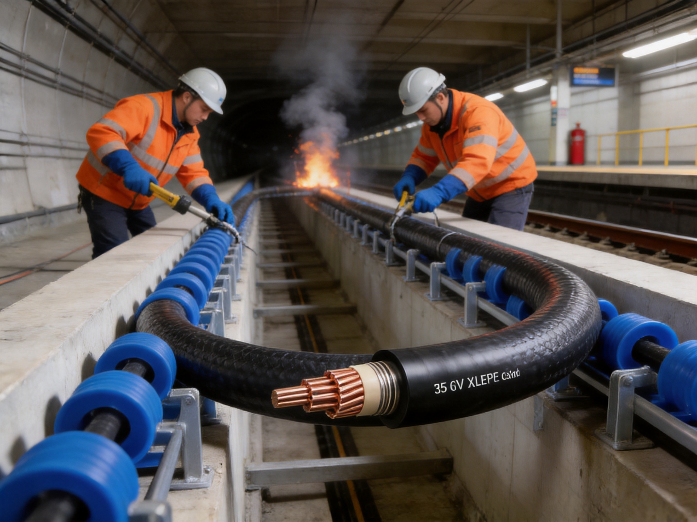
During installation, the pulling force should remain within the permitted value for the selected conductor and cable construction. Cable drums should be rotated in the correct direction, and the cable should not be dragged directly over sharp edges or contaminated surfaces. Rollers, corner guides, pulling socks, and tension-monitoring equipment can reduce damage during long installations.
After installation, the cable route should be inspected for sheath damage, excessive flattening, abrupt bends, unsupported weight, and contact with sharp structural members. Any defect should be assessed before energization.
7. Manufacturing Strengths and Quality-Control System
The performance of a specialized 35 kV cable depends heavily on manufacturing discipline. Advanced materials alone cannot guarantee reliability if the extrusion process, conductor preparation, cross-linking, screening, sheath application, or final testing is inconsistent.
Wuxi Guanghuan Cable Co., Ltd. was founded in 1998 and operates in Guanlin Town, Yixing City, Jiangsu Province. The company has more than 100,000 square meters of total site area, including more than 45,000 square meters of building area. Its production system includes more than 70 production and testing lines and a team of more than 140 employees, including over 30 technical professionals.
Integrated Production Capabilities
The manufacturer produces power cables, electrical equipment wires and cables, bare conductors, overhead insulated cables, high-speed railway and urban rail transit cables, energy-storage cables, photovoltaic cables, and wind-power cables. This broad product scope provides experience across different conductor technologies, insulation systems, sheath materials, voltage levels, and application conditions.
The company offers more than 100 product categories and over 30,000 specifications under its registered product brand. Such product breadth supports customized selection for large engineering projects where different cable families must work together across power distribution, control, equipment connection, and renewable-energy systems.
Process Monitoring
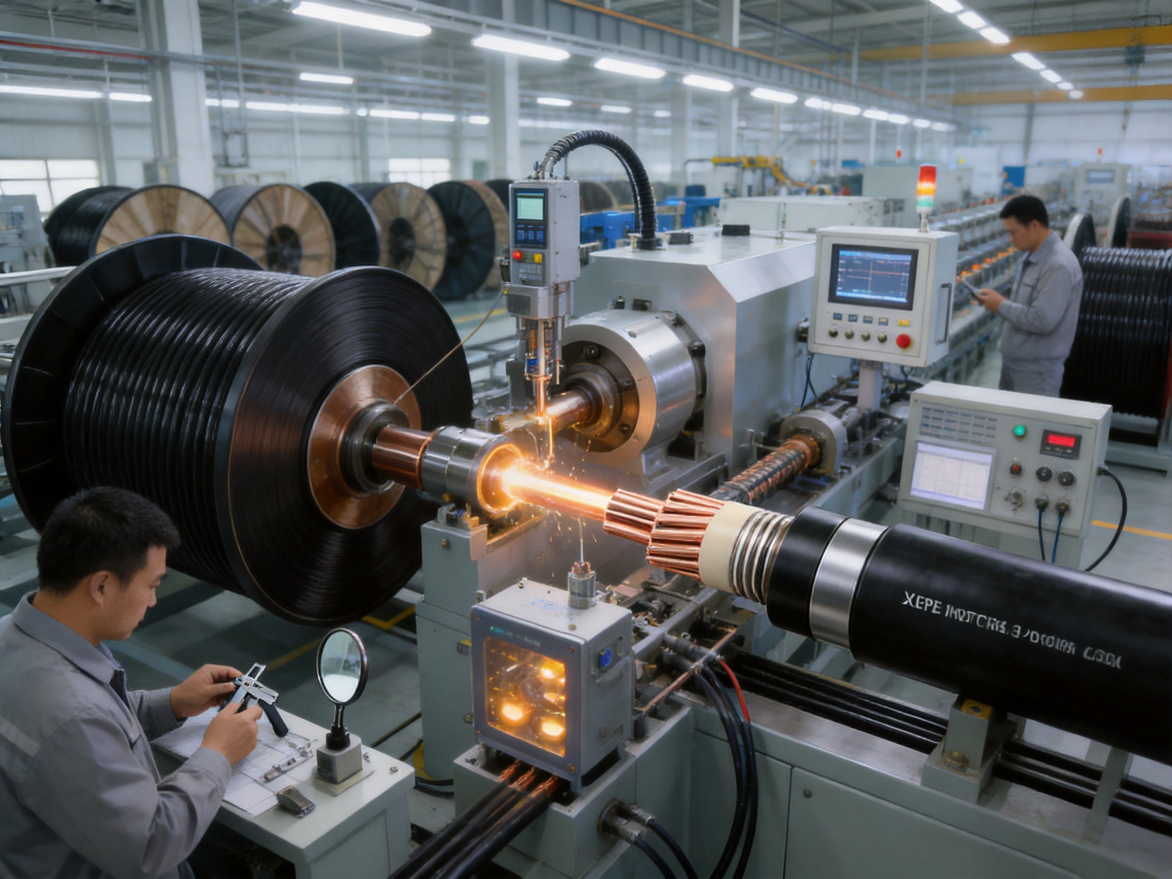
Medium-voltage cable production requires strict control of conductor dimensions, insulation thickness, eccentricity, surface quality, cleanliness, and material stability. Online eccentricity-monitoring equipment is used to help observe insulation uniformity during production. This is important because uneven insulation can create localized electric-field stress and reduce long-term dielectric reliability.
High-voltage series-resonance testing equipment supports high-voltage inspection of finished cable products. Partial-discharge detectors help identify internal defects, voids, contamination, protrusions, or other irregularities that could compromise insulation performance over time.
These controls are particularly significant for 35 kV cable because the cable may operate continuously in inaccessible areas. Detecting defects before shipment is more efficient and safer than discovering them after installation in a tunnel or station.
Quality Management and Certification
The company has obtained ISO 9001 quality-management certification, ISO 14001 environmental-management certification, ISO 45001 occupational-health-and-safety certification, and ISO 50001 energy-management certification. It has also obtained GB/T 29490 intellectual-property management certification, a green-management system certification, a social-responsibility management system certification, and an after-sales service management system certification.
These systems address more than final-product inspection. They cover procurement, production planning, process control, equipment management, environmental practices, worker safety, documentation, corrective action, and customer service. For infrastructure projects, a documented management system can improve traceability and reduce variation between production batches.
Products have also received certifications and qualifications including CCC, TÜV, product carbon-footprint certification, and China Energy-Saving and Environmentally Friendly Product recognition. The applicable certification should be confirmed for the specific cable model and project requirement.
Technical and Project Support
Large rail projects require more than a cable delivered to a construction site. They may require technical submittals, construction guidance, drum schedules, test reports, inspection support, installation recommendations, and assistance with model selection.
A manufacturer with experience in different cable categories can help coordinate conductor size, voltage class, sheath material, armoring, fire grade, biological protection, and delivery requirements. This reduces the possibility of selecting a cable that satisfies one requirement while overlooking another, such as tunnel fire behavior, minimum bending radius, or short-circuit coordination.
8. Advantages Compared with Conventional Cable Solutions
The 35 kV subway and urban rail transit cable offers several advantages when compared with general-purpose power cables that are not specifically designed for rail-transit conditions.
More Complete Safety Performance
A conventional cable may provide electrical transmission but lack the combination of low smoke, halogen-free performance, flame retardancy, and controlled acid-gas emission required in underground public infrastructure. This product integrates these properties into a cable intended for environments where passenger safety and emergency visibility are major concerns.
Better Protection Against Biological Attack
Ordinary cable sheaths may not be sufficiently resistant to termites or rodents. The specialized biological-resistance design reduces one of the less visible but important causes of cable failure in underground and trackside routes.
Greater Application Flexibility
The availability of different model structures, rated-voltage options, conductor sizes, armored and unarmored versions, and flame-retardant grades allows the cable to be adapted to different sections of a rail project. This is more flexible than relying on one general-purpose construction for every installation environment.
Improved Lifecycle Considerations
A cable with stronger environmental protection may reduce unscheduled maintenance, replacement work, service interruptions, and access requirements. In a subway, maintenance often requires possession of a track or closure of a station area. Preventing avoidable cable damage can therefore produce operational benefits beyond the initial purchase price.
Suitable for High-Requirement Projects
Urban rail transit projects typically require documented compliance, traceable production, stable quality, and reliable technical support. The manufacturer’s production facilities, testing equipment, management certifications, and broad experience support the type of quality assurance expected for infrastructure applications.
9. Application Scenarios
Subway Main Lines
The cable can be used in 35 kV power-supply networks serving subway lines. Depending on the electrical design, it may be installed between substations, along underground sections, or within power-distribution routes serving station and auxiliary systems.
Light Rail and Lightweight Track
Light rail and lightweight-track systems may include a combination of underground, surface, elevated, and outdoor sections. The cable’s ultraviolet protection, biological resistance, low-smoke design, and range of construction options make it suitable for varied route conditions, subject to project verification.
Urban Commuter Railways
Urban commuter railways require dependable power distribution across stations, depots, maintenance areas, and trackside facilities. The 35 kV cable can support medium-voltage networks where its electrical rating and mechanical construction match the system requirements.
Tunnels and Underground Platforms
Tunnels and platforms are among the most important application areas because ventilation can be restricted and access can be difficult. Low-smoke, halogen-free, flame-retardant, termite-resistant, and rodent-resistant properties are particularly valuable in such locations.
Trackside and Complex Environmental Areas
Trackside routes may be exposed to sunlight, moisture, soil movement, vegetation, pests, vibration, and accidental mechanical contact. A protective sheath with environmental stress-cracking resistance, ultraviolet protection, and biological resistance can provide an additional barrier against these conditions.
10. Selection and Project-Design Recommendations
Before ordering the cable, the project owner, designer, contractor, and cable manufacturer should review the complete technical requirement. Important selection items include rated voltage, conductor material, conductor cross-section, number of cores, armoring, screen arrangement, sheath material, fire classification, smoke requirement, halogen requirement, installation route, and biological-risk level.
The cable’s current-carrying capacity should be calculated for the actual installation method. Factors may include cable grouping, tunnel temperature, ventilation, soil thermal resistivity, duct arrangement, depth of burial, spacing, and emergency overload requirements.
Short-circuit calculations should include the conductor, metallic screen, protective device, fault-clearing time, and maximum permitted temperatures. The project should resolve any difference between short-circuit duration statements before final approval.
Installation drawings should show cable-bending locations, supports, cleats, connection boxes, terminal positions, fire barriers, penetrations, and separation from other services. The minimum bending radius should be checked using the actual outside diameter of the selected cable.
For underground and public-access areas, the fire-performance specification should clearly identify whether halogen-free or low-halogen cable is required, as well as the applicable flame-retardant grade. Fire performance should be coordinated with the overall tunnel and station fire strategy.
Where termite or rodent activity is possible, the project should identify whether biological resistance is required throughout the route or only in selected sections. Continuity of protection is important; a resistant cable may still be vulnerable if an unprotected joint, transition, or damaged sheath is left exposed.
11. Inspection, Testing, and Documentation
Before shipment, the cable should be checked against the purchase order, approved drawings, model designation, conductor size, voltage class, drum length, sheath marking, and test requirements. Factory test documents should be retained for project records.
Typical quality documentation may include conductor resistance results, dimensional checks, insulation and sheath test results, high-voltage test records, partial-discharge results where applicable, fire-performance data, material certificates, and inspection reports.
On arrival at the project site, cable drums should be inspected for impact, water entry, broken flanges, displaced end seals, and damage to markings. Drums should be stored on stable ground and protected from unnecessary exposure. Cable ends should remain sealed until preparation for installation.
After installation, testing may include sheath integrity checks, insulation-resistance measurements where applicable, conductor continuity checks, phase identification, and acceptance testing according to the project’s medium-voltage commissioning procedure. The exact test sequence and voltage should be determined by the approved standard and the responsible electrical engineer.
12. Frequently Asked Questions
What is the rated voltage of this cable?
The product is available with rated voltage designations U0/U of 21/35 kV and 26/35 kV. The correct designation should be selected according to the rail system’s electrical design and insulation-coordination requirements.
Where is this cable mainly used?
It is intended for subway, light rail, lightweight-track, urban commuter railway, tunnel, underground-platform, and related 35 kV power-distribution applications.
What makes the cable suitable for subway environments?
Its key subway-oriented features include low-smoke behavior, halogen-free or low-halogen options, flame retardancy, reduced acid-gas emission, termite resistance, rodent resistance, XLPE insulation, and a protective sheath designed for demanding environmental conditions.
What conductor sizes are available?
The production range covers power-cable cross-sections up to 630 mm². The final size should be selected according to load current, voltage drop, short-circuit current, installation conditions, and project standards.
What is the maximum continuous conductor temperature?
The maximum permissible continuous operating temperature of the conductor is 90°C under the stated technical conditions.
What is the maximum short-circuit temperature?
The stated maximum conductor temperature during a short circuit is 250°C. Because the supplied material contains different references for short-circuit duration, the project should confirm the applicable duration and calculation method with the manufacturer.
Is the cable halogen-free?
The product family includes halogen-free and low-halogen model options. The non-halogen version has a stated acid-gas emission limit of no higher than 5 mg/g, a pH value of not less than 4.3, and conductivity of no higher than 10 μS/mm under the relevant test conditions.
Can the cable be supplied with flame-retardant performance?
Yes. ZA, ZB, and ZC flame-retardant grades may be supplied according to the customer’s request and the project specification.
What is the minimum bending radius?
During installation, the minimum bending radius is 20D for unarmored single-core cable, 15D for armored single-core cable, 15D for unarmored three-core cable, and 12D for armored three-core cable. D means the outside diameter of the cable. Special limits apply near terminals and connection boxes.
Does the cable resist termites and rodents?
Yes. The cable models are designed with termite- and rodent-resistant protective characteristics. This makes them suitable for routes where biological attack is a known risk.
What testing supports the cable’s quality?
The product is manufactured and tested according to the stated enterprise standard, GB/T 12706.3-2020. Manufacturing quality is supported by process monitoring, high-voltage testing, partial-discharge detection, online eccentricity monitoring, and broader quality-management procedures.
Can the manufacturer support customized project requirements?
The product family includes different cable structures, voltage options, conductor cross-sections, fire grades, and armored or unarmored constructions. Project-specific requirements should be submitted for technical confirmation before ordering.
Conclusion
The 35 kV power cable for subway and urban rail transit is designed to address the combined electrical, fire-safety, mechanical, and environmental demands of modern rail infrastructure. Its 21/35 kV and 26/35 kV voltage options, XLPE insulation, copper conductor, conductor sizes up to 630 mm², and 90°C continuous operating temperature support reliable medium-voltage power transmission.
Its principal advantages over general-purpose cable solutions are the integration of low-smoke performance, halogen-free or low-halogen material options, flame retardancy, acid-gas control, termite resistance, rodent resistance, ultraviolet protection, and environmental stress-cracking resistance. These features are especially valuable in subway tunnels, underground stations, trackside routes, depots, and other locations where cable access is difficult and fire consequences can be severe.
The product is supported by the manufacturing capabilities of Wuxi Guanghuan Cable Co., Ltd., including extensive production and testing facilities, online process monitoring, high-voltage series-resonance testing, partial-discharge detection, and documented management systems. The company’s experience across power, railway, renewable-energy, and specialized cable products provides a foundation for supplying solutions to complex infrastructure projects.
For successful application, the cable must be selected and installed according to the complete project design. Rated voltage, current capacity, short-circuit duration, cable construction, fire classification, biological risk, bending radius, installation temperature, and testing requirements should all be confirmed before procurement. When these factors are properly coordinated, the cable provides a robust and safety-oriented solution for the power systems that keep urban rail transit moving.
References
1. GB/T 12706.3-2020, Power Cables with Extruded Insulation and Their Accessories for Rated Voltages from 6 kV up to 35 kV.
2. Technical product information for 35 kV power cable for subway and lightweight-track applications.
3. Manufacturer-provided technical data concerning rated voltage, conductor temperature, short-circuit performance, bending radius, fire performance, and cable construction.
4. Manufacturer quality-management and production information for power cables, railway cables, overhead conductors, and specialized cable products.
5. General engineering practices for medium-voltage cable selection, installation, testing, fire protection, and maintenance in urban rail transit systems.
Product: Power Cable for Subway and Urban Rail Transit (Rated Voltage 35kV)

-
Power Cable for Subway and Urban Rail Transit (Rated Voltage 35kV)
-
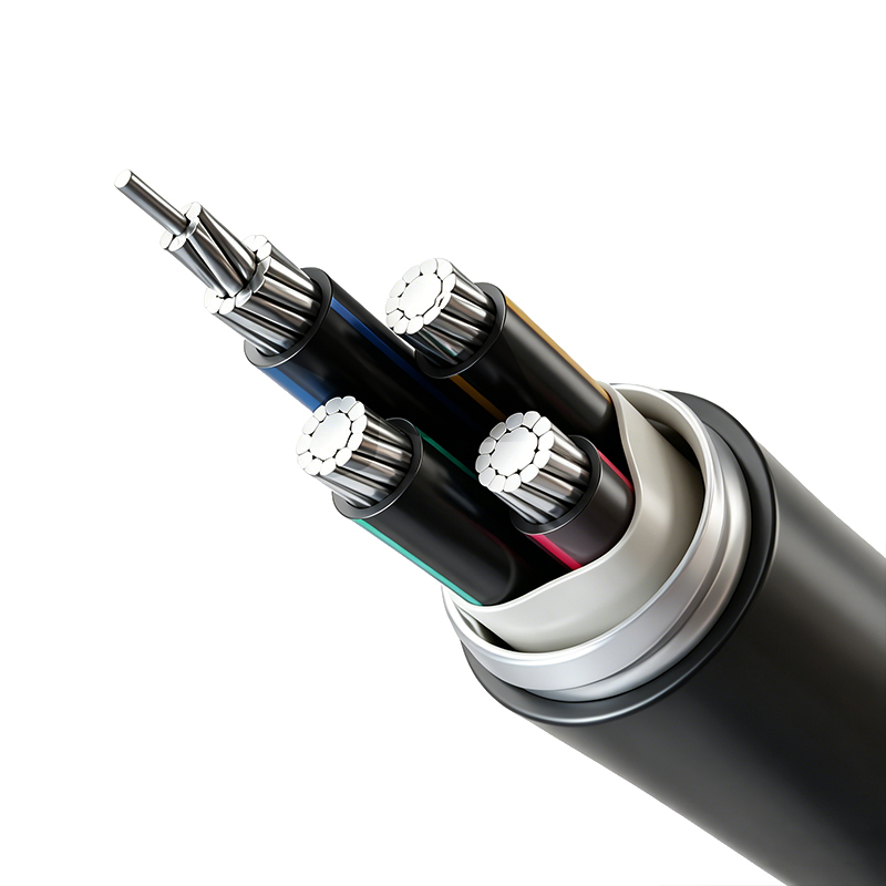
Aluminum Alloy Conductor Plastic Insulated Power Cable (Rated Voltage up to 26/35kV)
-
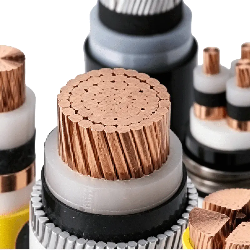
Rated Voltage 3.6/6kV–26/35kV XLPE Insulated Power Cable
-
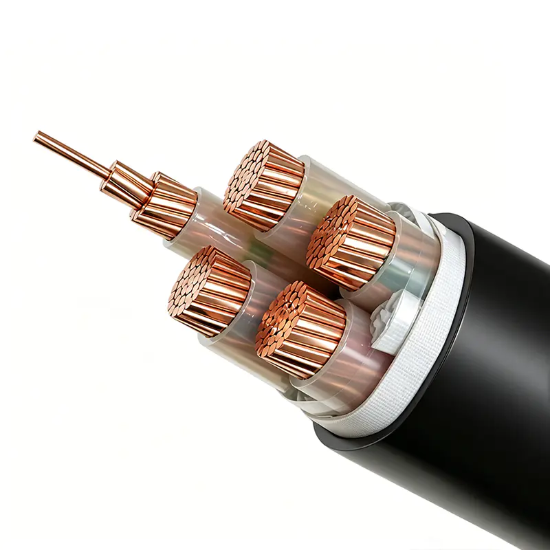
Rated Voltage 1.8/3kV XLPE Insulated Power Cable
-
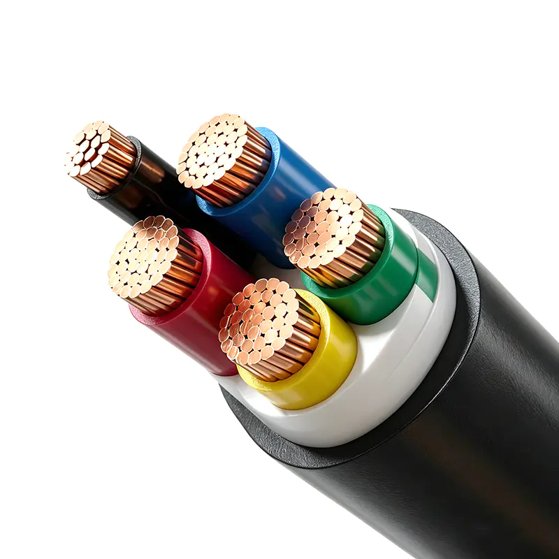
Rated Voltage 1.8/3kV PVC Insulated Power Cable

Copyright © Wuxi Guanghuan Cable Co., Ltd. All Rights Reserved. Power Cables Manufacturer Electrical Wire And Cable Factory

