


 English
 中文简体
 русский
 Español
 عربى

Rated Voltage 0.6/1kV XLPE Insulated Power Cable: Design, Performance, Applications, and Manufacturing Excellence
Content
- 1 1. Understanding the 0.6/1kV XLPE Power Cable
- 2 2. Why XLPE Insulation Is Preferred
- 3 3. Main Advantages Compared with Conventional Alternatives
- 4 4. Cable Construction and Functional Layers
- 5 5. Standard Cable Types and Applications
- 6 6. Available Core Configurations and Conductor Sizes
- 7 7. Electrical and Thermal Performance
- 8 8. Installation Environments
- 9 9. Advanced Manufacturing Processes
- 10 10. Manufacturing Strengths and Quality Assurance
- 11 11. Product Advantages for Engineering Projects
- 12 12. Cable Selection Guidelines
- 13 13. Installation and Handling Recommendations
- 14 14. Typical Applications
- 15 15. Q&A
- 15.1 Q1: What does 0.6/1kV mean?
- 15.2 Q2: Why is XLPE used instead of ordinary PVC insulation?
- 15.3 Q3: What is the maximum continuous operating temperature?
- 15.4 Q4: Can the cable be installed directly in the ground?
- 15.5 Q5: What is the difference between steel tape armor and steel wire armor?
- 15.6 Q6: Which is better, copper conductor or aluminum conductor?
- 15.7 Q7: Can armored single-core cables be used in AC systems?
- 15.8 Q8: What is the minimum bending radius?
- 15.9 Q9: What standards apply to this cable?
- 15.10 Q10: What current-carrying factors must be considered?
- 15.11 Q11: Are flame-retardant and fire-resistant versions available?
- 15.12 Q12: How does the manufacturer support customized projects?
- 16 16. Why Manufacturer Capability Matters
- 17 17. Conclusion
- 18 References
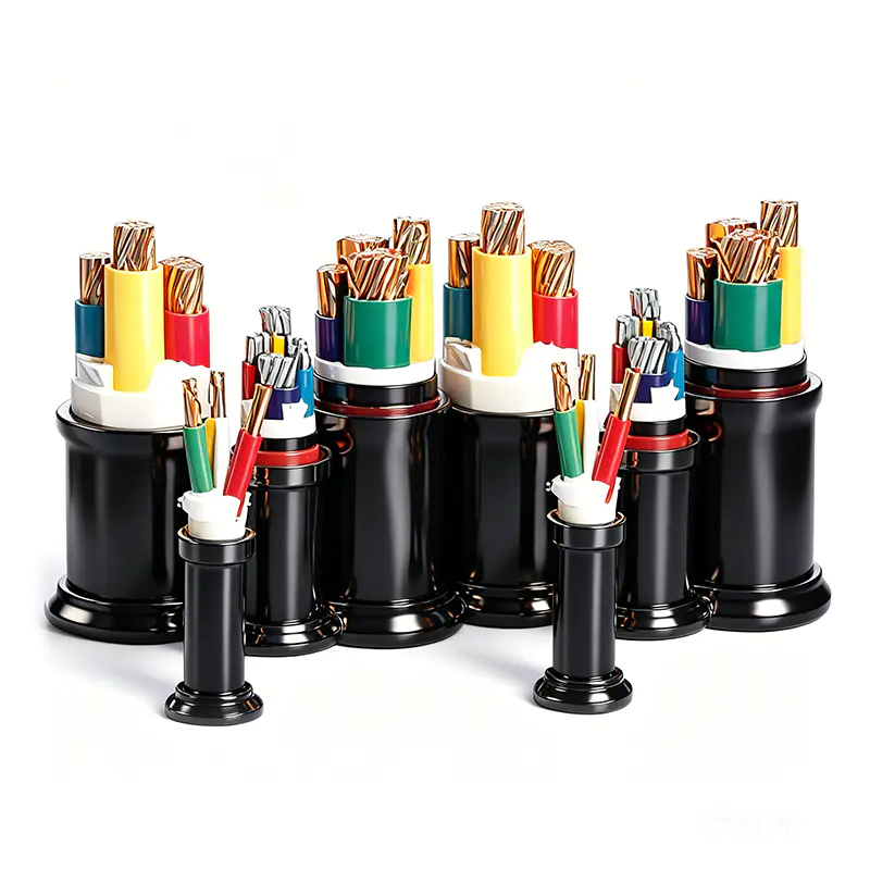
- 19 Product: Rated Voltage 0.6/1kV XLPE Insulated Power Cable
Reliable power distribution depends on cable systems that can carry electrical energy safely, efficiently, and continuously under demanding operating conditions. Rated voltage 0.6/1kV cross-linked polyethylene insulated power cable is one of the most widely used solutions for low-voltage distribution networks, industrial facilities, commercial buildings, infrastructure projects, tunnels, cable trenches, and direct-buried installations. Its combination of high operating temperature, strong insulation performance, flexible construction options, and resistance to environmental stress makes it a practical choice for modern electrical installations.
This cable is engineered around XLPE insulation, a thermosetting material produced by transforming polyethylene from a linear molecular structure into a three-dimensional cross-linked network. The resulting insulation has greater thermal stability, improved mechanical properties, lower dielectric loss, and better resistance to moisture and environmental influences than many traditional insulation materials. These characteristics help the cable maintain reliable performance over a long service life.
The 0.6/1kV designation identifies the cable’s rated voltage between conductor and earth and between conductors, respectively. In fixed electrical installations, the cable can be selected in copper or aluminum conductor configurations, with PVC or PE outer sheaths, and with optional steel tape or steel wire armoring. This broad product range allows engineers and contractors to match cable construction with load requirements, installation conditions, mechanical risks, and fire-safety objectives.
Manufactured according to GB/T 12706.1 and related conductor requirements under GB/T 3956, this cable can be supplied for national-standard projects and adapted to international specifications when requested. Careful control of conductor quality, insulation extrusion, dimensional accuracy, electrical testing, sheathing, and final inspection supports dependable performance from production through installation.
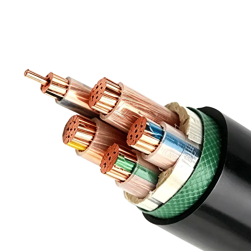
Rated Voltage 0.6/1kV XLPE Insulated Power Cable
1. Understanding the 0.6/1kV XLPE Power Cable
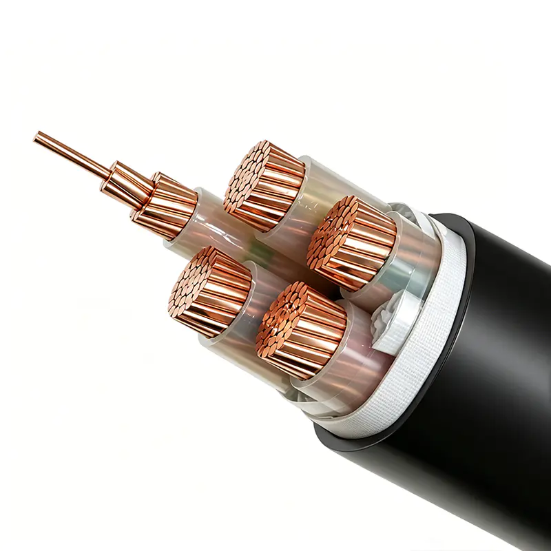
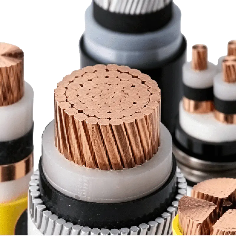
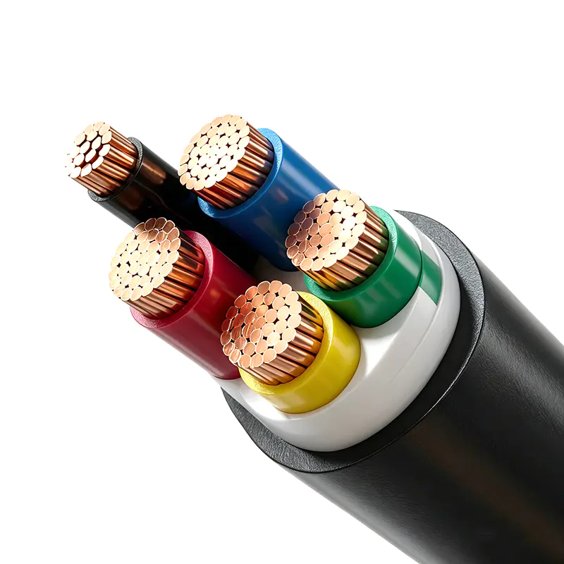
A power cable is more than a conductive metal core covered by an insulating layer. It is a coordinated system consisting of a conductor, insulation, fillers, binding materials, optional inner sheath, optional armor, and an external protective sheath. Each component performs a specific function, and the performance of the complete cable depends on the compatibility and quality of all layers.
In a 0.6/1kV XLPE insulated power cable, the conductor carries the electrical current. The conductor may be manufactured from high-purity copper or aluminum. Copper offers excellent conductivity, compact construction, and strong mechanical performance. Aluminum provides a lower-weight and often more economical alternative for applications in which the installation design allows a larger conductor cross-section.
The XLPE insulation surrounds the conductor and separates it electrically from other cores, metallic layers, and the external environment. It is designed for a maximum continuous conductor operating temperature of 90°C. Under short-circuit conditions, with a maximum duration of five seconds, the conductor temperature may reach up to 250°C without exceeding the specified cable limit.
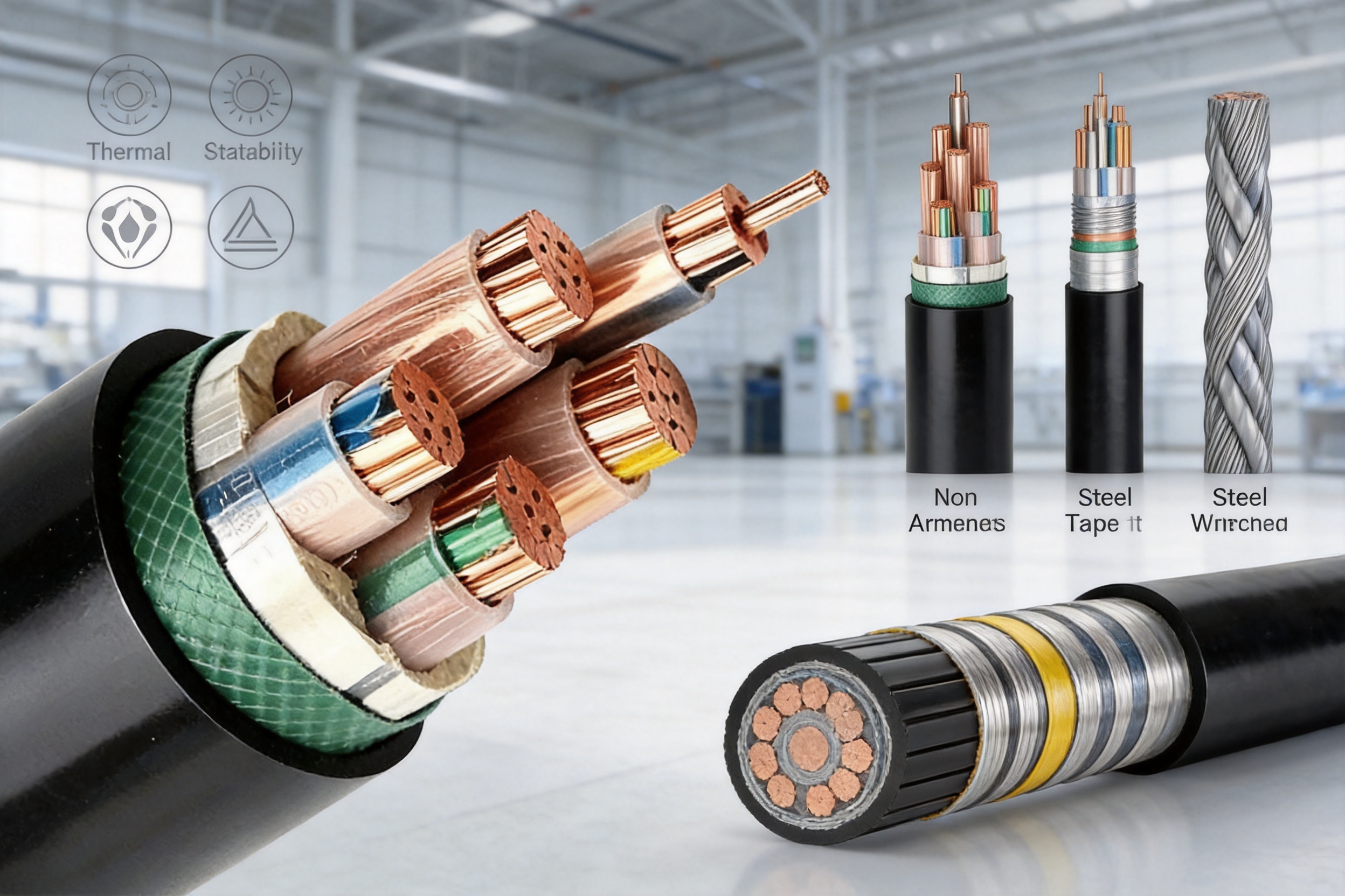
Depending on the selected cable type, the cable may include no armor, steel tape armor, or fine steel wire armor. Non-armored versions are generally selected for installations where the cable is protected from significant external mechanical forces. Steel tape armored versions provide enhanced resistance to compression and are suitable for many buried, trench, and building installations. Steel wire armored versions provide greater resistance to tensile forces and are useful where pulling stress or mechanical loading is expected.
The outer sheath is commonly made from PVC or PE. PVC provides a balanced combination of mechanical strength, wear resistance, corrosion resistance, and cost efficiency. PE offers favorable moisture resistance and weathering performance and may be selected for installations requiring particular environmental protection. Flame-retardant, low-smoke halogen-free, and fire-resistant versions may also be produced according to project requirements.
2. Why XLPE Insulation Is Preferred
XLPE has become a preferred insulation material for power cables because it provides a strong balance between electrical, thermal, mechanical, and environmental performance. Traditional PVC-insulated cables remain useful in many applications, but XLPE cables generally provide a higher permissible continuous conductor temperature and improved resistance to thermal aging.
Higher Continuous Operating Temperature
The maximum long-term conductor operating temperature of this cable is 90°C. This is a significant advantage in comparison with many conventional PVC-insulated power cables, which commonly have a lower continuous operating temperature. A higher permissible temperature allows the cable to carry more current for a comparable conductor size, subject to the applicable installation conditions and correction factors.
Higher thermal capability is especially valuable in industrial plants, high-rise buildings, commercial complexes, and infrastructure projects where electrical loads may fluctuate or where cable routes have limited space. By selecting the proper conductor cross-sectional area and applying the correct installation correction factors, designers can optimize the cable system without compromising safety.
Improved Insulation Stability
The cross-linked molecular structure gives XLPE insulation greater resistance to deformation at elevated temperatures. The insulation maintains its shape and electrical integrity under normal operating conditions and during short-duration overload or fault events. This stability helps reduce the possibility of insulation displacement, localized thinning, or thermal damage when the cable is correctly selected and installed.
Low Dielectric Loss
XLPE has low dielectric loss and high insulation resistance. These properties help reduce energy loss associated with the insulation system and support stable operation in distribution networks. Although a 0.6/1kV cable is generally used in low-voltage systems, low dielectric loss remains beneficial in long cable routes, industrial installations, and systems where energy efficiency is a design priority.
Resistance to Moisture and Environmental Stress
Properly manufactured XLPE insulation resists moisture penetration and maintains reliable electrical performance in a wide range of environments. When combined with a suitable PVC or PE sheath, the cable can be used indoors, in tunnels, cable trenches, shafts, and direct-buried installations. The correct sheath and armor selection remains essential because environmental resistance depends on the complete cable construction, not insulation alone.
Long-Term Service Reliability
XLPE power cables are designed for long-term fixed installation. Their thermal stability, insulation strength, and resistance to aging support consistent performance over many years when the cable is operated within its specified limits. Manufacturing quality is particularly important because defects in insulation thickness, concentricity, cleanliness, or cross-linking can influence the service life of the finished cable.
3. Main Advantages Compared with Conventional Alternatives
The 0.6/1kV XLPE insulated power cable offers several practical advantages over conventional low-voltage cable constructions. These benefits are not limited to the insulation material; they also arise from the availability of different conductor materials, sheath materials, armor types, core arrangements, and fire-performance options.
Greater Current-Carrying Potential
Because the conductor may operate continuously at up to 90°C, the cable can provide a higher current-carrying capacity than a comparable cable with a lower permissible conductor temperature. The actual rating depends on conductor material, conductor size, number of loaded cores, cable grouping, ambient temperature, soil thermal resistivity, installation depth, and heat dissipation.
For example, the reference installation conditions for air installation include an ambient temperature of 40°C and a maximum conductor temperature of 90°C. For direct burial, the reference conditions include a soil temperature of 25°C, soil thermal resistivity of 2.0 K·m/W, and a burial depth of 0.7 meters. These reference conditions provide a basis for calculating current ratings, while actual projects require correction factors whenever conditions differ.
Broader Installation Flexibility
The cable can be supplied in non-armored, steel tape armored, and steel wire armored constructions. Non-armored cables are appropriate for protected indoor routes, tunnels, and cable trenches where external mechanical forces are limited. Steel tape armored cables are suitable where compression resistance and protection against ordinary mechanical impact are required. Steel wire armored cables are selected where the cable may experience pulling force, tension, or more demanding mechanical conditions.
Both copper and aluminum conductor options are available. Copper is often preferred where space is restricted or where high conductivity and compact dimensions are important. Aluminum may be selected for long distribution routes, larger cable systems, or projects where overall cable weight and material cost must be controlled.
Stable Performance in Difficult Routes
Compared with some less robust cable constructions, the XLPE cable provides dependable performance in routes exposed to temperature variation, moisture, vibration, and mechanical handling. With the appropriate sheath and armor, it can be installed in tunnels, shafts, trenches, and soil. This flexibility reduces the need to use different basic cable technologies for every part of a distribution project.
Efficient Installation and Maintenance
The cable has a relatively simple and well-established structure. Its core components are familiar to installers, electrical contractors, and maintenance teams. The availability of standard cable types, including YJV, YJLV, YJY, YJLY, YJV22, YJLV22, YJV32, and YJLV32, simplifies specification and procurement.
Correct handling remains essential. The cable should be transported on suitable drums, protected from severe impact, and installed without exceeding its minimum bending radius. For this product, the minimum bending radius should generally not be less than 15 times the cable outer diameter unless a specific approved design or product specification states otherwise.
4. Cable Construction and Functional Layers
4.1 Conductor
The conductor is manufactured from copper or aluminum that complies with the applicable requirements of GB/T 3956. Conductor quality directly affects resistance, voltage drop, power loss, heat generation, and current-carrying capability. A conductor with consistent cross-sectional area and controlled lay characteristics also supports stable insulation extrusion and improved cable geometry.
Copper conductors provide lower electrical resistance for a given cross-sectional area and are often selected for compact installations, high-load circuits, and applications requiring excellent connection performance. Aluminum conductors have lower density and can reduce cable weight. Because aluminum has higher electrical resistivity than copper, an appropriately larger aluminum cross-section may be required to achieve the desired electrical performance.
4.2 XLPE Insulation
The insulation is extruded around the conductor under carefully controlled conditions. The XLPE layer must have uniform thickness, a smooth interface with the conductor, and freedom from contaminants, voids, protrusions, and mechanical damage. The cross-linking process must be controlled to achieve the required thermal and electrical properties.
Insulation quality is evaluated through dimensional checks, insulation resistance measurement, voltage testing, and other routine or type tests required by the applicable standard. Consistent extrusion temperature, clean material handling, stable line speed, and accurate diameter control are important elements of the manufacturing process.
4.3 Filling and Binding Tape
For multicore cables, non-hygroscopic fillers are placed between the insulated cores to maintain a round cable shape and stabilize the internal construction. A non-woven binding tape is then applied to secure the cores and fillers. These layers support a uniform outer profile, improve handling, and help the inner sheath or outer sheath form a consistent protective covering.
4.4 Inner Sheath
An optional inner sheath may be used to separate the insulated cores from the armor. This layer protects the insulation during armoring, fills irregular spaces, and creates a stable surface for the application of steel tape or steel wires. Its presence is particularly useful in armored cable constructions designed for direct burial or mechanically demanding routes.
4.5 Armor
Steel tape armor is commonly selected for protection against compression and ordinary external mechanical forces. Steel wire armor provides greater tensile strength and is suitable for cable routes where pulling or longitudinal stress may occur. Armor selection should always reflect the installation method, expected mechanical loads, fault conditions, and local electrical regulations.
Single-core armored cables require special consideration in alternating-current systems. Magnetic armor can cause induced currents, additional losses, and heating. Therefore, armored single-core cables are generally intended for direct-current systems unless non-magnetic armor or suitable magnetic isolation measures are used. This design rule must be addressed during system planning rather than after installation.
4.6 Outer Sheath
The outer sheath protects the cable against moisture, abrasion, chemical exposure, sunlight, and ordinary mechanical damage. PVC and PE sheaths are available for different project requirements. The sheath color and marking can also assist with product identification, installation management, and traceability.
5. Standard Cable Types and Applications
The product family covers several common cable types. The letter “YJ” identifies XLPE insulation, while the following letters and numbers identify conductor material, sheath material, and armor construction. The exact selection should be based on the electrical design, environmental conditions, mechanical risks, and applicable standards.
| Type | Construction | Typical Application |
|---|---|---|
| YJV | Copper conductor, XLPE insulation, PVC sheath | Indoor installation, tunnels, and cable trenches where significant external mechanical force is not expected. |
| YJLV | Aluminum conductor, XLPE insulation, PVC sheath | Indoor and protected distribution routes where reduced cable weight or material economy is important. |
| YJY | Copper conductor, XLPE insulation, PE sheath | Routes requiring a PE outer sheath and good moisture or weather resistance. |
| YJLY | Aluminum conductor, XLPE insulation, PE sheath | Distribution installations using aluminum conductors and PE sheath protection. |
| YJV22 | Copper conductor, XLPE insulation, steel tape armor, PVC sheath | Indoor, tunnel, trench, or direct-buried installation where compression resistance is required but large pulling force is not expected. |
| YJLV22 | Aluminum conductor, XLPE insulation, steel tape armor, PVC sheath | Mechanically protected distribution routes using an aluminum conductor. |
| YJV23 | Copper conductor, XLPE insulation, steel tape armor, PE sheath | Buried or outdoor routes requiring both steel tape armor and a PE sheath. |
| YJLV23 | Aluminum conductor, XLPE insulation, steel tape armor, PE sheath | Protected outdoor and buried installations with an aluminum conductor. |
| YJV32 | Copper conductor, XLPE insulation, fine steel wire armor, PVC sheath | Routes requiring resistance to external mechanical forces and a degree of tensile strength. |
| YJLV32 | Aluminum conductor, XLPE insulation, fine steel wire armor, PVC sheath | Mechanically demanding routes where aluminum conductors are suitable. |
| YJV33 | Copper conductor, XLPE insulation, fine steel wire armor, PE sheath | Outdoor, buried, tunnel, or shaft installations requiring wire armor and a PE sheath. |
| YJLV33 | Aluminum conductor, XLPE insulation, fine steel wire armor, PE sheath | Protected outdoor and buried applications using aluminum conductors. |
Non-armored cable types are generally chosen for locations where cable trays, conduits, building structures, or other protective measures limit mechanical risk. Steel tape armored cables are commonly selected for direct burial and trench installations. Steel wire armored cables are useful in vertical shafts, long pulling routes, and locations where the cable may be subjected to greater tensile stress.
6. Available Core Configurations and Conductor Sizes
The product range supports one-core, two-core, three-core, four-core, five-core, and multi-core configurations such as three-core plus one, four-core plus one, and three-core plus two. These arrangements allow the cable to be matched to three-phase systems, neutral requirements, protective conductor arrangements, and specialized distribution architectures.
For copper conductors, available nominal cross-sectional areas generally range from 1.5 to 800 square millimeters for single-core constructions, depending on the specified cable type. Multicore versions are available in a range that may extend from 1.5 square millimeters to 630 square millimeters for three-core and selected combined-core constructions.
Aluminum conductor versions generally begin at larger sizes, such as 10 square millimeters, and may extend to 800 square millimeters for single-core constructions and 630 square millimeters for selected multicore configurations. The final range depends on the number of cores, armor construction, sheath type, and customer requirements.
Choosing a conductor size requires more than comparing the expected load current with a nominal ampacity table. Engineers should consider voltage drop, short-circuit withstand, installation arrangement, ambient temperature, grouping, soil thermal resistivity, harmonic current, prospective fault current, and future load growth. The cable manufacturer can provide detailed technical data and correction factors for project-specific calculations.
7. Electrical and Thermal Performance
Rated Voltage
The cable has a power-frequency rated voltage of U0/U equal to 0.6/1kV. It is designed for fixed installation in distribution networks and industrial installations operating at power-frequency voltages up to this level. It is suitable for alternating-current systems when the cable type and installation method are selected correctly.
Conductor Resistance
Maximum conductor direct-current resistance at 20°C is controlled according to the applicable conductor standard. Representative copper resistance values include 12.1 ohms per kilometer for 1.5 square millimeters, 7.41 ohms per kilometer for 2.5 square millimeters, 1.83 ohms per kilometer for 10 square millimeters, 0.153 ohms per kilometer for 120 square millimeters, and 0.0221 ohms per kilometer for 800 square millimeters.
Representative aluminum values include 3.08 ohms per kilometer for 10 square millimeters, 1.20 ohms per kilometer for 25 square millimeters, 0.320 ohms per kilometer for 95 square millimeters, 0.125 ohms per kilometer for 240 square millimeters, and 0.0367 ohms per kilometer for 800 square millimeters. Actual production values must comply with the applicable standard and the selected conductor class.
Power-Frequency Voltage Test
For a 0.6/1kV cable, the power-frequency AC withstand test voltage is 3.5kV for five minutes without breakdown. The product information also identifies a 6.5kV for five minutes test level for 1.8/3kV cable designs. Test conditions, sampling procedures, and acceptance criteria should be confirmed against the applicable product standard and customer specification.
Short-Circuit Performance
During a short circuit lasting no more than five seconds, the conductor temperature should not exceed 250°C. Short-circuit performance depends on conductor material, conductor cross-sectional area, insulation properties, fault duration, and the effectiveness of the protection system. Cable sizing should therefore be coordinated with circuit-breaker or fuse clearing times and the calculated prospective fault current.
Current-Carrying Capacity
Current-carrying capacity is not a fixed number independent of installation. Heat generated by the conductor must be dissipated through the insulation, sheath, surrounding air or soil, and any neighboring cables. Installation in air usually permits greater heat dissipation than closely grouped or poorly ventilated routes. Direct burial performance depends strongly on soil temperature, thermal resistivity, burial depth, moisture, and cable spacing.
For air installation, the reference ambient temperature is 40°C. Typical correction factors for other ambient temperatures are 1.18 at 20°C, 1.14 at 25°C, 1.09 at 30°C, 1.05 at 35°C, 1.00 at 40°C, 0.94 at 45°C, and 0.90 at 50°C.
For direct burial, the reference soil temperature is 25°C. Typical soil-temperature correction factors are 1.08 at 15°C, 1.04 at 20°C, 1.00 at 25°C, 0.96 at 30°C, 0.92 at 35°C, 0.88 at 40°C, and 0.83 at 45°C. Additional factors may be required for soil thermal resistivity, cable spacing, burial depth, parallel circuits, and seasonal conditions.
8. Installation Environments
Indoor Distribution
Inside commercial buildings, residential developments, factories, and utility rooms, non-armored YJV or YJLV cables can be installed in trays, conduits, shafts, and cable channels where mechanical protection is already provided. The cable’s 90°C conductor temperature rating supports high-density distribution layouts when ventilation and grouping are properly considered.
Tunnels and Cable Trenches
Tunnels and cable trenches may expose cables to moisture, dust, vibration, restricted ventilation, and limited access for maintenance. A suitable sheath and, where necessary, armor can protect the cable from the surrounding environment. Cable spacing, heat accumulation, drainage, fire protection, and access for inspection should be incorporated into the route design.
Direct Burial
Armored cable types such as YJV22, YJLV22, YJV23, and YJLV23 are commonly considered for direct-buried routes. The cable must be laid at a suitable depth, with attention to bedding material, backfill quality, warning tape, separation from other utilities, and protection at road crossings. The actual soil thermal characteristics should be reviewed because poor heat dissipation can reduce current-carrying capacity.
Vertical Shafts
Vertical cable routes may create significant tensile forces, especially during installation or when long cable lengths are supported from one point. Fine steel wire armored cables can provide greater tensile resistance than steel tape armored constructions. The cable support system must be designed to carry the cable weight without transferring excessive stress to terminations or joints.
Alternating-Current and Direct-Current Systems
In AC systems, the installation of single-core cables requires special attention to magnetic effects. Magnetic metallic armor surrounding a single-core AC cable can produce circulating currents, additional heat, and increased losses. Non-magnetic armor or suitable magnetic isolation should be used where armoring is required. Armored single-core cables may be used in DC systems, subject to the applicable design and safety requirements.
9. Advanced Manufacturing Processes
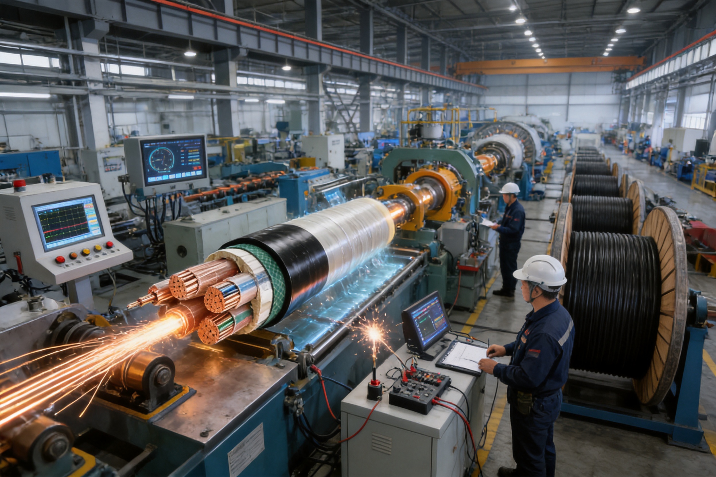
Product performance begins with manufacturing discipline. A high-quality cable factory must control raw materials, production parameters, equipment condition, environmental cleanliness, inspection procedures, and final documentation. The manufacturing process for this 0.6/1kV XLPE cable integrates conductor processing, insulation extrusion, cross-linking, cable assembly, armoring, sheathing, testing, and traceability.
Raw Material Inspection
Copper rods, aluminum rods, XLPE insulation compounds, PVC or PE sheath materials, steel tape, steel wires, fillers, and binding tapes are inspected before entering production. Material verification may include visual inspection, dimensional checks, electrical resistance, mechanical properties, moisture control, and conformity documentation.
Strict raw-material management reduces the risk of inconsistent conductor resistance, insulation contamination, unstable extrusion, sheath cracking, and premature aging. Materials are stored in conditions that protect them from moisture, dust, excessive heat, and accidental mixing between different grades.
Conductor Processing
Metal rods are drawn, annealed where required, and stranded into the specified conductor construction. Drawing equipment must maintain stable dimensions and surface quality. Stranding machines control lay length, tension, compactness, and concentricity. These parameters affect conductor flexibility, resistance, cable diameter, and the quality of the insulation interface.
Online monitoring and process inspection help identify deviations before they become part of a long production length. Conductor resistance is tested to verify compliance, while dimensional checks confirm that the conductor is suitable for the next production stage.
Clean-Room Insulation Extrusion
XLPE insulation extrusion is one of the most important stages in the cable manufacturing process. The conductor passes through a crosshead where insulation material is applied in a controlled, uniform layer. Extrusion temperature, pressure, line speed, material flow, and cooling conditions must remain stable.
Clean production conditions are especially important for medium- and high-voltage cable manufacturing, but they also contribute to the quality of low-voltage XLPE cable. Foreign particles, moisture, surface imperfections, and geometric irregularities can reduce insulation reliability. Online diameter and eccentricity monitoring supports immediate process adjustment and helps maintain consistent insulation thickness.
Cross-Linking and Cooling
The XLPE material undergoes a controlled cross-linking process that creates the thermosetting molecular network responsible for its high thermal performance. Correct temperature and pressure profiles are required to ensure complete and uniform cross-linking. Afterward, the insulated conductor is cooled under controlled conditions to stabilize its dimensions and prevent damage.
Insulation samples may be evaluated for tensile strength, elongation, aging behavior, insulation resistance, and dimensional compliance. These checks help verify that the material has achieved the required physical and electrical properties.
Cabling and Assembly
For multicore cables, insulated cores are assembled with fillers and binding tape. The cabling line must maintain the designed lay length and core arrangement. Excessive tension can deform the insulation or create internal stress, while insufficient tension can produce an unstable cable profile.
A stable round profile is important for subsequent inner-sheath extrusion, armoring, outer-sheath application, drum winding, installation, and termination. Process operators inspect the cable surface and geometry during production to identify defects as early as possible.
Armoring and Sheathing
Steel tape or steel wire is applied with controlled tension and overlap. Correct armor tension ensures mechanical protection without damaging the inner layers. The external sheath is then extruded over the assembly. Sheath thickness, concentricity, surface smoothness, marking clarity, and spark-test performance are controlled during this stage.
The final sheath must be strong enough to withstand handling and installation while remaining sufficiently flexible for the specified bending requirements. PVC and PE compounds are selected and processed according to their intended environmental and mechanical performance.
Online Inspection and Final Testing
Modern cable production benefits from online eccentricity monitors, diameter gauges, spark testers, temperature controls, and production data systems. These tools allow process deviations to be detected during manufacture rather than after the full cable length has been completed.
Final testing may include conductor resistance measurement, insulation resistance testing, power-frequency voltage testing, dimensional inspection, sheath checks, marking verification, and visual examination. Type tests, sample tests, and routine tests are performed according to the applicable standard, product type, and customer requirements.
10. Manufacturing Strengths and Quality Assurance
Wuxi Guanghuan Cable Co., Ltd. operates as an established cable manufacturer with experience in power cables, electrical equipment wires, bare conductors, overhead insulated cables, rail transit cables, energy-storage cables, photovoltaic cables, and wind-power cable solutions. Its broad product portfolio supports technical coordination across multiple cable categories and application environments.
The company operates more than 70 production and testing lines and employs technical professionals responsible for product development, process control, testing, and quality management. A manufacturing base covering more than 100,000 square meters provides space for production, inspection, material storage, engineering support, and logistics management.
Advanced equipment, including online eccentricity monitoring systems, high-voltage series-resonance testers, and partial-discharge detection equipment, supports the company’s quality-control approach. These technologies help evaluate cable geometry, insulation integrity, electrical withstand performance, and process consistency.
The company has obtained management-system certifications including ISO 9001 for quality management, ISO 14001 for environmental management, ISO 45001 for occupational health and safety, and ISO 50001 for energy management. Additional certifications and management systems cover intellectual property, green management, social responsibility, and after-sales service.
Product certifications and qualifications include CCC, TÜV-related approvals for applicable products, product carbon-footprint credentials, and energy-saving or environmentally friendly product certifications where relevant. Project-specific certification requirements should always be confirmed before ordering because certification scope may vary by product family, voltage level, conductor material, and destination market.
The company’s experience in large-scale production and technical service allows it to support customized conductor materials, core arrangements, sheath selections, armor constructions, fire-performance requirements, and international standards. This flexibility is valuable for projects that require more than a standard catalog cable.
11. Product Advantages for Engineering Projects
Reliable Electrical Performance
Controlled conductor resistance, uniform XLPE insulation, and routine voltage testing help provide stable electrical performance. Engineers can use the cable in fixed low-voltage distribution systems with confidence that the product is manufactured to recognized technical requirements.
Reduced Thermal Constraints
The 90°C continuous conductor rating gives designers additional thermal capacity compared with many traditional cable alternatives. This can be useful in compact cable routes, high-load circuits, and installations where heat dissipation must be carefully managed.
Flexible Material Selection
The availability of copper and aluminum conductors gives project teams control over conductivity, weight, space, and material cost. PVC and PE sheath choices allow the cable to be adapted to indoor, outdoor, buried, humid, and mechanically demanding environments.
Mechanical Protection Options
Steel tape and steel wire armors provide different mechanical advantages. Selecting the correct armor can improve resistance to compression, impact, tension, and installation stress. This reduces the risk of cable damage during handling and service.
Broad Size and Core Range
The wide range of conductor cross-sections and core configurations supports small building circuits as well as large industrial and infrastructure feeders. The availability of three-core plus one, four-core plus one, and three-core plus two constructions can simplify system design where neutral or protective conductor arrangements require a dedicated configuration.
Adaptability to Fire-Safety Requirements
Flame-retardant, low-smoke halogen-free, and fire-resistant constructions can be supplied when required. These options are particularly relevant to public buildings, transportation facilities, high-rise structures, tunnels, hospitals, data centers, and other projects where smoke generation and circuit continuity are important safety considerations.
12. Cable Selection Guidelines
The correct cable should be selected through a coordinated electrical, mechanical, environmental, and installation review. The following factors should be assessed before final specification.
Load Current and Voltage Drop
Determine the design current, expected demand factor, motor starting current, harmonic content, and allowable voltage drop. Select conductor material and cross-sectional area based on both ampacity and voltage-drop calculations. A cable that satisfies ampacity may still be unsuitable if its voltage drop is excessive over a long route.
Installation Method
Identify whether the cable will be installed in air, on a tray, in a conduit, in a tunnel, in a shaft, in a trench, or directly in the ground. Each method changes heat dissipation and mechanical exposure. Direct burial generally requires suitable armor, bedding, depth, and correction factors.
Environmental Conditions
Consider ambient temperature, soil temperature, moisture, chemical exposure, ultraviolet radiation, flooding risk, corrosive substances, vibration, and the presence of rodents or construction activity. PVC and PE sheath materials may be selected according to the expected environment.
Mechanical Loading
Where the cable may be compressed, impacted, pulled, or suspended vertically, select an appropriate armor construction. Steel tape armor is not a substitute for tensile armor in a route with significant pulling force. Similarly, steel wire armor may be unnecessary in a protected indoor tray installation.
Fire and Smoke Requirements
Determine whether the project requires flame retardancy, low smoke and halogen-free performance, fire resistance, or a special fire-survival duration. These requirements should be specified before manufacturing because they influence the insulation, sheath, filler, tape, and overall cable construction.
AC Single-Core Arrangements
For single-core cables in AC circuits, assess magnetic effects and armor material. Non-magnetic armor or magnetic isolation measures may be required. Cable spacing and arrangement should also be designed to control circulating currents, electromagnetic forces, and heat accumulation.
13. Installation and Handling Recommendations
Cable quality can be compromised by poor handling. Drums should be stored on firm, level ground and protected from impact, water accumulation, and unauthorized movement. The cable ends should remain sealed to prevent moisture ingress. During transportation, drums should be lifted using appropriate equipment and should not be rolled in a direction that could loosen the cable winding.
Before installation, verify the cable type, conductor material, number of cores, cross-sectional area, length, sheath marking, and test documentation. Inspect the outer sheath for cuts, abrasion, crushing, or other damage. If damage is discovered, the affected area should be evaluated and repaired or rejected according to the applicable procedure.
During pulling, the force should be controlled and applied through suitable pulling equipment. The cable should not be dragged directly over sharp surfaces. Rollers, guides, corner supports, and approved pulling accessories should be used to maintain the minimum bending radius and avoid sidewall pressure.
The installation temperature should not be lower than 0°C unless special procedures approved for the specific cable construction are followed. Cold conditions can reduce sheath flexibility and increase the risk of cracking during bending. Cables should be allowed to reach a suitable temperature before installation where necessary.
After laying, cable ends should be protected until termination. Terminations and joints must be compatible with the conductor material, insulation system, voltage rating, and cable size. Aluminum conductors require connectors and preparation methods specifically designed for aluminum to control oxidation and connection resistance.
Testing after installation may include continuity checks, conductor resistance measurement, insulation resistance testing, sheath integrity testing, phase identification, and appropriate withstand testing. The testing program should be determined by the project engineer and applicable electrical standards.
14. Typical Applications
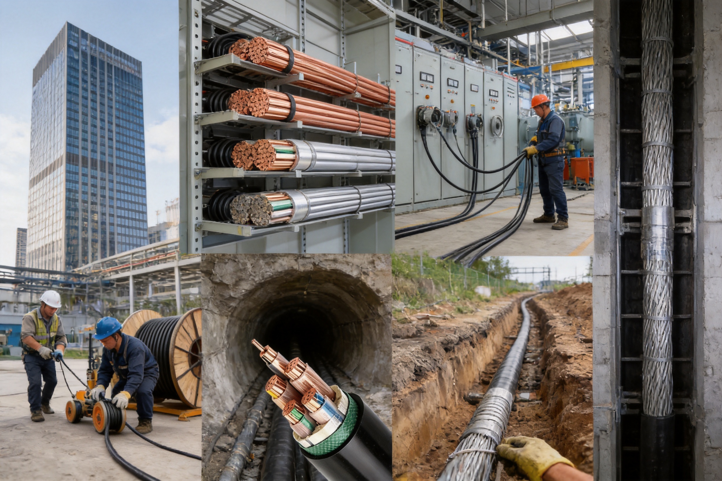
In high-rise buildings and residential communities, the cable can be used for main distribution feeders, sub-distribution circuits, fire-pump supplies, mechanical equipment, and general building services. The selection of fire-performance options, core arrangement, and armor depends on the building design and local regulations.
Industrial plants require cables that can withstand continuous operation, equipment starting currents, vibration, dust, and varied installation conditions. Copper or aluminum XLPE cables can be used for motor feeders, plant distribution, transformer connections, process equipment, and auxiliary systems when correctly sized.
Mines and infrastructure facilities often include long routes, buried sections, tunnels, shafts, and areas with increased mechanical risk. Armored constructions provide additional protection, while wire armor may be appropriate for vertical or tension-bearing sections.
Commercial complexes, warehouses, logistics centers, and data-support facilities benefit from cable systems that combine high current-carrying capability with manageable installation dimensions. Low-smoke halogen-free or flame-retardant options may be specified where evacuation safety and equipment protection are priorities.
Renewable-energy, energy-storage, and industrial electrification projects may use 0.6/1kV XLPE cable in auxiliary distribution, low-voltage collection, control-power, and equipment-connection systems. The cable must be selected according to the specific electrical environment, direct-current or alternating-current configuration, temperature, and installation method.
15. Q&A
Q1: What does 0.6/1kV mean?
The designation refers to the rated power-frequency voltage between conductor and earth and between conductors. The cable is intended for fixed installations in systems with a rated voltage of 0.6/1kV.
Q2: Why is XLPE used instead of ordinary PVC insulation?
XLPE provides a higher maximum continuous conductor operating temperature, strong insulation resistance, low dielectric loss, improved thermal stability, and good resistance to environmental stress. It is therefore suitable for many demanding distribution and industrial applications.
Q3: What is the maximum continuous operating temperature?
The maximum permissible long-term conductor temperature is 90°C. During a short circuit lasting no more than five seconds, the conductor temperature should not exceed 250°C.
Q4: Can the cable be installed directly in the ground?
Yes. Suitable armored constructions, such as steel tape armored or steel wire armored versions, can be selected for direct burial. The design must also account for burial depth, soil thermal resistivity, soil temperature, cable spacing, mechanical protection, and local installation regulations.
Q5: What is the difference between steel tape armor and steel wire armor?
Steel tape armor mainly improves resistance to compression and external mechanical force. Steel wire armor provides greater tensile resistance and is more suitable for routes where pulling force, suspension, or longitudinal mechanical stress is expected.
Q6: Which is better, copper conductor or aluminum conductor?
Neither is universally better. Copper offers higher conductivity and a more compact design, while aluminum provides lower density and can reduce cable weight and material cost. The choice depends on electrical requirements, installation space, connection technology, project budget, and applicable standards.
Q7: Can armored single-core cables be used in AC systems?
They can be used only when the armor and installation arrangement are designed to prevent harmful magnetic effects. Non-magnetic armor or magnetic isolation may be required. Magnetic armor around single-core AC cables can cause circulating currents and additional heating.
Q8: What is the minimum bending radius?
The bending radius should generally not be less than 15 times the cable outer diameter. The cable manufacturer’s specific installation instructions should be followed for the selected construction and operating condition.
Q9: What standards apply to this cable?
The product is manufactured in accordance with GB/T 12706.1 for cables rated at 1kV and 3kV, with conductor requirements associated with GB/T 3956. International-standard versions can be supplied according to customer requirements.
Q10: What current-carrying factors must be considered?
Important factors include ambient air temperature, soil temperature, soil thermal resistivity, burial depth, cable spacing, number of parallel circuits, installation arrangement, conductor material, number of loaded cores, and maximum permissible conductor temperature.
Q11: Are flame-retardant and fire-resistant versions available?
Yes. Flame-retardant, low-smoke halogen-free, and fire-resistant constructions can be provided according to project requirements. The required performance should be defined during the design and procurement stage.
Q12: How does the manufacturer support customized projects?
The manufacturer can coordinate conductor material, conductor size, core arrangement, sheath material, armor type, fire-performance characteristics, standards, testing, and documentation. Customized production should be confirmed through a technical specification before the order is finalized.
16. Why Manufacturer Capability Matters
Power cable reliability is closely related to production capability. A supplier with broad manufacturing experience can manage the interaction between conductor design, insulation extrusion, cabling, armor, sheathing, testing, packaging, and delivery. This reduces the risk that one layer will be optimized while another creates a hidden weakness.
Large-scale production capacity also helps support consistent delivery for major building, industrial, utility, and infrastructure projects. Multiple production and testing lines provide flexibility for different cable sizes and constructions, while technical personnel can assist with selection, current-rating calculations, installation conditions, and compliance documentation.
Integrated quality management is equally important. ISO-certified systems provide a framework for controlling procedures, records, corrective actions, supplier management, environmental performance, and customer service. However, certification should be supported by actual process controls, inspection capability, equipment maintenance, and transparent test documentation.
A manufacturer with experience in power, renewable-energy, rail transit, and industrial cable applications can also understand the different priorities of each project. For example, a buried infrastructure project may prioritize mechanical protection and moisture resistance, while a high-rise building may emphasize fire performance, smoke reduction, compact routing, and installation coordination.
17. Conclusion
The rated voltage 0.6/1kV XLPE insulated power cable is a versatile and reliable solution for modern low-voltage power distribution. Its cross-linked polyethylene insulation provides a 90°C continuous conductor temperature rating, strong electrical performance, low dielectric loss, and good resistance to thermal and environmental stress. Copper and aluminum conductors, PVC and PE sheaths, multiple core arrangements, and steel tape or steel wire armors allow the cable to be configured for a wide range of applications.
Its advantages over many conventional alternatives include higher thermal capability, broad installation flexibility, reliable insulation stability, adaptable mechanical protection, and support for flame-retardant, low-smoke halogen-free, and fire-resistant designs. These advantages are realized only when the cable is correctly specified, installed, and operated within its design limits.
Manufacturing quality is central to product performance. Controlled raw materials, precise conductor processing, clean XLPE extrusion, uniform cross-linking, accurate cabling, carefully applied armor, reliable sheathing, online monitoring, and complete electrical testing all contribute to long-term service reliability.
With extensive cable manufacturing experience, broad production capacity, advanced testing equipment, technical personnel, and certified management systems, Wuxi Guanghuan Cable Co., Ltd. is positioned to provide standard and customized cable solutions for power distribution, industrial installations, buildings, tunnels, direct-buried routes, infrastructure, and emerging energy applications.
For any project, the final cable selection should be based on a complete review of load current, voltage drop, installation environment, mechanical exposure, thermal conditions, fire-safety requirements, system voltage, conductor material, and applicable standards. When these factors are properly coordinated, the 0.6/1kV XLPE insulated power cable can provide efficient, safe, and durable service throughout the life of the electrical installation.
References
GB/T 12706.1, Power Cables with Extruded Insulation and Their Accessories for Rated Voltages of 1kV and 3kV.
GB/T 3956, Conductors of Insulated Cables.
International Electrotechnical Commission, Electric Cables and Current-Carrying Capacity Guidance.
International Electrotechnical Commission, Power Cable Installation and Electrical Testing Principles.
ISO 9001, Quality Management Systems: Requirements.
ISO 14001, Environmental Management Systems: Requirements with Guidance for Use.
ISO 45001, Occupational Health and Safety Management Systems: Requirements with Guidance for Use.
ISO 50001, Energy Management Systems: Requirements with Guidance for Use.
Manufacturer technical information for 0.6/1kV XLPE insulated power cable, including cable construction, production range, conductor resistance, installation conditions, current-rating factors, and testing requirements.
Product: Rated Voltage 0.6/1kV XLPE Insulated Power Cable


Copyright © Wuxi Guanghuan Cable Co., Ltd. All Rights Reserved. Power Cables Manufacturer Electrical Wire And Cable Factory

