


 English
 中文简体
 русский
 Español
 عربى

Photovoltaic Cable: Engineering Reliable DC Power Transmission for Solar Energy Systems
Content
- 1 Introduction to Photovoltaic Cable Technology
- 2 Role of PV Cable in a Solar Power Plant
- 3 PV1-F and H1Z2Z2-K Cable Types
- 4 Standards and International Applicability
- 5 Conductor Design and Oxidation Protection
- 6 Double-Layer Insulation and Sheath System
- 7 Resistance to Outdoor Environmental Stress
- 8 Temperature Performance and Thermal Stability
- 9 Electrical Ratings and System Compatibility
- 10 Flexibility and Minimum Bending Radius
- 11 Current-Carrying Capacity
- 12 Service Life and Lifecycle Value
- 13 Manufacturing Strengths and Quality Management
- 14 Advantages Compared with General-Purpose Cable Options
- 15 Applications in Different Solar Environments
- 16 Installation and Maintenance Considerations
- 17 Selection Guide for Project Engineers
- 18 Quality Assurance from Raw Material to Finished Cable
- 19 Environmental Responsibility and Safety
- 20 Frequently Asked Questions
- 20.1 What is photovoltaic cable used for?
- 20.2 What is the difference between PV1-F and H1Z2Z2-K?
- 20.3 Why is tinned copper used in solar cable?
- 20.4 Can photovoltaic cable be installed outdoors?
- 20.5 What does LSZH mean?
- 20.6 What is the expected service life of the cable?
- 20.7 How should cable size be selected?
- 20.8 Can the cable be used in coastal areas?
- 20.9 Why is the bending radius important?
- 20.10 What testing capability does the manufacturer have?
- 21 Conclusion
- 22 References
- 23 Product: Photovoltaic Cable (PV Cable)
Introduction to Photovoltaic Cable Technology
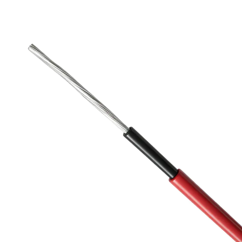
Photovoltaic cable is a specialized cable designed for the direct-current side of solar power generation systems. It connects photovoltaic modules, string circuits, combiner boxes, DC distribution equipment, and inverters, forming one of the most important electrical links in a solar installation. Although photovoltaic cables may appear simple compared with modules, inverters, or mounting structures, their long-term reliability has a direct influence on energy yield, operational safety, maintenance costs, and the service life of the complete photovoltaic plant.
Solar installations expose cables to conditions that are considerably more demanding than those found in ordinary indoor electrical systems. Cables may be installed on rooftops, mounted beneath solar modules, laid on the ground, suspended in open air, routed through cable trays, or buried in environments affected by moisture and chemicals. During their service life, they can experience ultraviolet radiation, ozone, high humidity, rain, dust, salt spray, temperature cycling, mechanical vibration, and repeated thermal expansion and contraction.
A conventional building wire is generally not designed for this combination of environmental and electrical stresses. Photovoltaic cable therefore requires specialized conductor treatment, insulation, sheath materials, dimensional design, flexibility, flame performance, and aging resistance. The PV1-F and H1Z2Z2-K cable types described in this article are developed for these requirements and are manufactured in accordance with recognized photovoltaic cable standards.
Wuxi Guanghuan Cable Co., Ltd. manufactures photovoltaic cables as part of a broader portfolio that includes power cables, electrical equipment wires, bare conductors, overhead insulated cables, rail transit cables, energy storage cables, and wind power cables. Its experience in cable design, conductor processing, insulation extrusion, testing, and quality control supports the production of cables intended for demanding renewable-energy applications.
The key value of a high-quality photovoltaic cable is not limited to its nominal voltage or cross-sectional area. A suitable cable must maintain electrical insulation, mechanical integrity, and dimensional stability throughout years of outdoor operation. It must also be easy to install, compatible with photovoltaic connectors and equipment, and capable of supporting the current requirements of modern solar arrays. These combined characteristics distinguish dedicated PV cable from general-purpose electrical cable.
Photovoltaic Cable (PV Cable)
Role of PV Cable in a Solar Power Plant
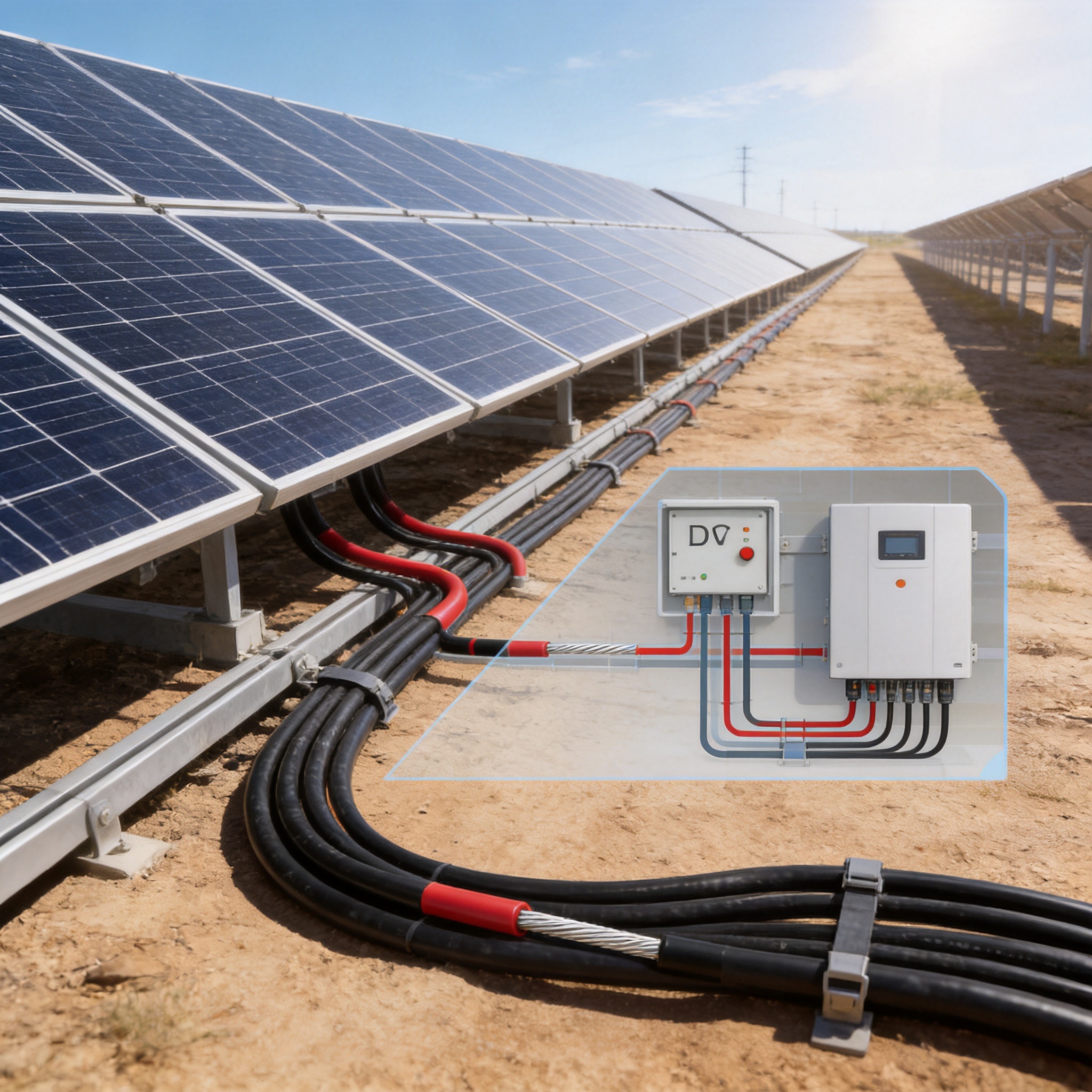
A photovoltaic system normally contains several electrical sections. The first section is the module interconnection circuit. Individual solar modules are connected in series to form strings, allowing the voltage to reach the required operating level. The second section includes string wiring and combiner boxes, where multiple strings may be grouped and protected. The third section consists of DC trunk lines that carry power from the array to the inverter. The inverter then converts DC electricity into AC electricity for use, storage, or grid transmission.
Photovoltaic cable is used throughout the DC portion of this arrangement. Short lengths may connect neighboring modules, while longer lengths may connect module strings to combiner boxes or route power from field arrays to centralized inverters. In rooftop applications, cables are often installed below modules where airflow is limited and temperatures may be higher than the surrounding ambient air. In utility-scale projects, cables may be exposed to open-air sunlight, ground contact, dust, water, and mechanical movement.
The DC side of a solar system presents specific hazards. Unlike an AC circuit that passes through zero current during each cycle, a photovoltaic DC circuit can continue producing an arc when a connection is damaged or disconnected under load. Proper cable selection, connector compatibility, circuit protection, routing, and installation are therefore essential. A cable with stable insulation and a durable sheath helps reduce the probability of insulation breakdown, leakage current, and short circuits.
Because photovoltaic plants are expected to operate for decades, cable replacement can be expensive and disruptive. A failure may require the isolation of a string, removal of modules, excavation of buried cable, use of lifting equipment, or shutdown of an entire generation section. Selecting a cable designed for long-term outdoor service can reduce the risk of these costs and improve the overall availability of the plant.
PV1-F and H1Z2Z2-K Cable Types
The product range includes PV1-F and H1Z2Z2-K photovoltaic cables. Both are single-core solar cables intended for DC power transmission in photovoltaic systems, but their applicable standards and production ranges differ.
Cable type |
Primary standard |
Rated voltage |
Core configuration |
Cross-sectional range |
PV1-F |
2PfG 1169/08.2007 |
DC 1.8 kV; AC 0.6/1.0 kV |
Single core |
1.5–35 mm² |
H1Z2Z2-K |
EN 50618:2014 |
DC 1.5 kV; AC 1.0/1.0 kV |
Single core |
1.5–240 mm² |
PV1-F is widely used for module connections, string circuits, and compact DC wiring applications. Its available cross-sectional range covers common low- and medium-current photovoltaic connections. H1Z2Z2-K extends the range to larger sizes and can be used for higher-current photovoltaic circuits and longer DC trunk lines, subject to the project design, installation method, voltage drop calculation, and applicable regulations.
The choice between cable types should be based on the project specification and the standard required by the owner, designer, certification authority, or local electrical code. Other factors include system voltage, short-circuit current, ambient temperature, grouping, installation method, cable length, connector type, and expected future loading.
Standards and International Applicability
Photovoltaic cables must be evaluated against standards that address electrical performance, insulation, sheath properties, mechanical durability, resistance to environmental exposure, and fire-related characteristics. The cable products described here are manufactured with reference to the German photovoltaic cable standard 2PfG 1169/08.2007 and the European standard EN 50618:2014.
Compliance with a recognized standard provides a technical framework for design and testing. It helps define conductor resistance, voltage rating, insulation thickness, sheath requirements, heat resistance, low-temperature behavior, aging performance, and other characteristics. This is especially important for international photovoltaic projects, where project documents often specify a particular standard or certification system.
Standards do not replace correct engineering design or installation. A cable may satisfy its product standard but still be unsuitable if it is incorrectly sized, installed beyond its permitted bending radius, exposed to incompatible chemicals, or connected using unsuitable terminals. The cable, connector, protection device, inverter, and installation method must be considered as one complete electrical system.
For export-oriented projects, standard alignment also makes technical review easier. Engineering contractors, procurement teams, inspectors, and project owners can compare cable specifications using recognized terminology and test requirements. This reduces uncertainty during approval and helps ensure that the selected cable is appropriate for the intended operating environment.
Conductor Design and Oxidation Protection
The conductor is made from high-purity electrical-grade tinned copper wire. Copper provides high electrical conductivity and comparatively low resistance, while tinning adds a protective layer to the surface of each copper strand. This combination is particularly beneficial in outdoor solar installations where humidity, condensation, and corrosive contaminants may be present.
Untreated copper can gradually oxidize when exposed to moisture and atmospheric pollutants. Oxidation may increase contact resistance and reduce the quality of terminations. In severe conditions, corrosion can progress at exposed strands, crimped connections, or damaged areas. Tinned copper helps limit this process and supports more stable electrical connections over time.
The tin layer also improves soldering performance and contributes to corrosion resistance. Although photovoltaic systems commonly use crimped connectors rather than soldered module terminations, good surface characteristics remain important during conductor processing and connection assembly. Properly prepared conductor strands can help produce consistent crimping and reliable contact pressure.
Conductor design also affects flexibility. Photovoltaic cables are frequently routed around module frames, through clips, along support rails, and into junction boxes. A stranded conductor is more flexible than a solid conductor of the same cross-sectional area. This flexibility simplifies installation and reduces excessive mechanical stress at connection points, provided the cable is handled according to the manufacturer’s instructions.
Compared with non-tinned general-purpose copper cable, tinned photovoltaic conductor offers a stronger defense against the combined effects of moisture and outdoor exposure. This is one of the product’s important advantages in coastal regions, humid climates, agricultural areas, and utility-scale solar sites where long-term environmental stability is essential.
Double-Layer Insulation and Sheath System
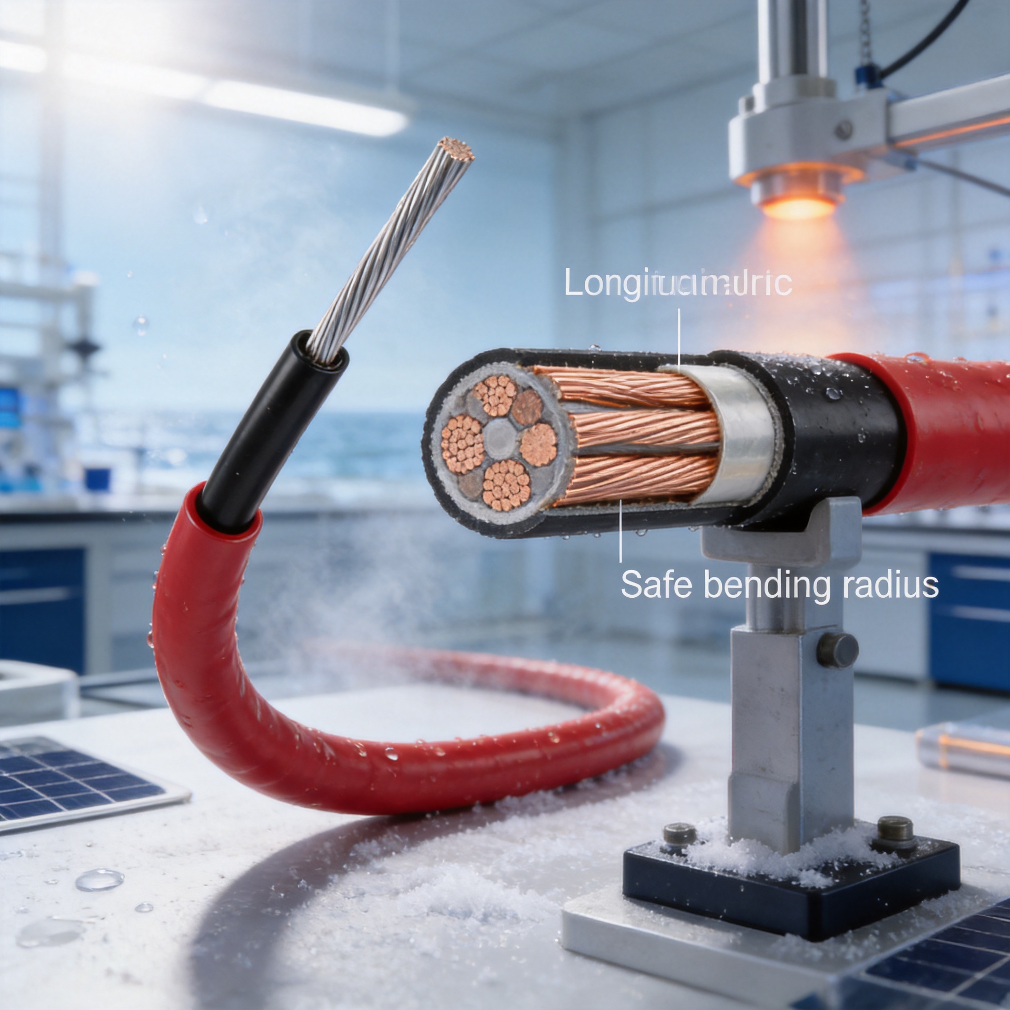
The cable uses cross-linked insulation and sheath materials based on low-smoke zero-halogen cross-linked polyolefin, commonly identified as LSZH XLPO. The insulation provides electrical separation between the conductor and the surrounding environment, while the outer sheath protects the cable against mechanical damage, moisture, ultraviolet radiation, and environmental aging.
Cross-linking changes the structure of the polymer and improves its resistance to heat, deformation, and aging. Compared with ordinary thermoplastic materials, cross-linked polyolefin can maintain its physical and electrical properties over a wider operating range. This is valuable in photovoltaic applications because cables may heat significantly under strong sunlight and high current loading.
The double-layer structure provides an additional level of protection. If the outer sheath experiences surface wear or limited mechanical damage, the inner insulation remains an important electrical barrier. The two layers must be manufactured with uniform thickness, good adhesion where required, and consistent concentricity around the conductor. Online monitoring and dimensional inspection are therefore important parts of production control.
LSZH materials are designed to produce low smoke and avoid the release of toxic halogen gases during combustion. This characteristic is valuable in buildings, tunnels, transport facilities, enclosed electrical rooms, and other locations where smoke density and corrosive gases could threaten people or equipment. It also supports the environmental objectives often associated with renewable-energy projects.
The low-smoke zero-halogen design can provide a practical advantage over cables using conventional halogenated sheath materials. In the event of a fire, reducing smoke and corrosive gases may improve visibility, reduce damage to nearby equipment, and assist evacuation and emergency response. The exact fire performance remains dependent on the complete cable design, installation arrangement, and applicable test classification.
Resistance to Outdoor Environmental Stress
Outdoor solar cables must retain their properties despite exposure to ultraviolet radiation. UV energy can cause polymer surfaces to become brittle, discolored, cracked, or weakened. A damaged sheath may allow moisture ingress and reduce the mechanical protection of the insulation. The photovoltaic cable’s cross-linked polyolefin materials are selected to provide strong resistance to UV aging during long-term outdoor use.
Ozone is another environmental factor that can affect certain insulating materials. Ozone exposure may lead to surface cracking, especially when a material is simultaneously subjected to mechanical stress. The cable design is intended to resist ozone erosion and maintain its protective function in open-air installations.
The cable is also designed for resistance to acids and alkalis. Solar power plants may be located near industrial facilities, agricultural land, deserts, or coastal areas where airborne contaminants and chemicals vary considerably. Resistance to these substances helps preserve the sheath and insulation when the cable is exposed to challenging local conditions.
Moisture resistance is important in every photovoltaic installation. Cables may experience rain, dew, condensation, splash water, or temporary contact with wet ground. The conductor tinning, insulation system, and sheath work together to reduce the risk of corrosion and water-related deterioration. Nevertheless, cables should still be routed and supported to prevent unnecessary water accumulation and mechanical abrasion.
In coastal installations, salt-laden air can accelerate corrosion of metallic components and electrical connections. Tinned copper conductors and appropriately selected polymer materials help improve resistance to this environment. Correct connector selection, sealing, and installation remain equally important because the cable cannot compensate for an unsuitable or poorly assembled connection.
Temperature Performance and Thermal Stability
The cable is designed for stable operation within an ambient temperature range of approximately -40°C to +90°C. The maximum continuous conductor operating temperature can reach 120°C, and the conductor can withstand an instantaneous short-circuit temperature of up to 200°C for a period of up to five seconds, subject to the applicable product design and installation requirements.
Temperature performance is critical because solar cables often operate in locations where the cable temperature is substantially higher than the surrounding air. Dark surfaces, limited ventilation beneath modules, direct solar radiation, and high electrical loading can combine to raise the conductor temperature. If a cable is not designed for these conditions, insulation aging can accelerate and current-carrying capacity may be reduced.
The cross-linked insulation system helps the cable resist softening and deformation at elevated temperatures. It also supports stable dielectric performance during repeated daily thermal cycles. At night, the cable may cool rapidly, while daytime operation can produce significant heating. Repeated expansion and contraction can stress materials and connections, making flexibility and dimensional stability important.
At low temperatures, cable materials must remain flexible enough for installation and service. A brittle sheath may crack when the cable is uncoiled, bent, or moved in cold weather. The stated low-temperature capability supports installation and operation in cold climates, although installers should follow recommended handling procedures and avoid forcing cable bends when the material is below its permitted handling temperature.
Designers must calculate current-carrying capacity using the actual installation conditions rather than relying only on the nominal cable size. Ambient temperature, grouping, cable spacing, sunlight, installation surface, conduit conditions, and soil thermal properties can all affect heat dissipation. Correct derating is essential for safe and efficient operation.
Electrical Ratings and System Compatibility
The PV1-F cable supports a rated voltage of DC 1.8 kV and AC 0.6/1.0 kV according to the stated product range. The H1Z2Z2-K cable supports DC 1.5 kV and AC 1.0/1.0 kV. These ratings make the cables suitable for many modern photovoltaic systems, including high-voltage DC architectures designed to reduce current and transmission losses.
Higher system voltage can allow a solar plant to transmit a given amount of power at lower current. Lower current may reduce conductor losses and permit more efficient long-distance DC collection. However, system voltage selection must be coordinated with module configuration, inverter ratings, insulation coordination, connectors, switchgear, surge protection, and local electrical regulations.
Voltage rating is only one part of cable selection. The cable must also have adequate current capacity and insulation performance under the worst expected operating conditions. Designers should consider maximum power current, short-circuit current, ambient temperature, cable length, voltage drop, parallel circuits, and possible future changes to the system.
The cable’s insulation system is intended to provide reliable separation between the conductor and the environment during normal operation. Proper routing and termination are required to preserve this performance. Sharp edges, excessive pulling force, uncontrolled twisting, and unsupported cable weight can damage the insulation or place stress on connectors.
Flexibility and Minimum Bending Radius
Photovoltaic arrays contain many closely spaced modules and support structures. Cables must often change direction around frames, follow rail systems, enter junction boxes, and pass through equipment cabinets. A flexible cable reduces installation effort and helps installers achieve clean, organized routing.
The minimum bending radius of the product is not less than four times the cable’s outer diameter under the stated product characteristics. Maintaining this radius helps prevent excessive stress on the conductor, insulation, and sheath. It also reduces the likelihood of deformation that could affect connector assembly or long-term mechanical performance.
Cold-bending and cold-winding performance are especially useful during installation in low-temperature climates. Cables that remain manageable in cold conditions can be deployed more efficiently and with less risk of surface cracking. Installers should still avoid abrupt bending, repeated flexing at the same point, or placing a bend directly at a connector body.
Flexibility can provide an advantage over stiff general-purpose power cables in module-level wiring. It can reduce installation time, simplify routing, improve appearance, and lower the chance of unsupported loops rubbing against metal structures. Good routing also helps prevent water traps and minimizes the effect of wind-induced movement.
Current-Carrying Capacity
Current-carrying capacity depends on how effectively heat can escape from the cable. The supplied technical data gives reference values for a 60°C ambient temperature and a maximum conductor temperature of 120°C. These values are intended for engineering guidance and must be adjusted when actual environmental or installation conditions differ.
Nominal cross-sectional area |
Single cable in free air |
Single cable on ground surface |
Parallel cables on ground surface |
1.5 mm² |
30 A |
29 A |
24 A |
2.5 mm² |
40 A |
39 A |
33 A |
4 mm² |
55 A |
52 A |
44 A |
6 mm² |
70 A |
67 A |
57 A |
10 mm² |
98 A |
93 A |
79 A |
16 mm² |
132 A |
125 A |
107 A |
25 mm² |
176 A |
167 A |
142 A |
35 mm² |
218 A |
207 A |
176 A |
The table demonstrates why installation method matters. A cable installed in free air can generally dissipate heat more effectively than a cable placed directly on a surface or grouped with other loaded cables. Parallel cable arrangements may experience additional thermal interaction, requiring a lower permissible current than a single isolated cable.
For H1Z2Z2-K cable sizes from 50 mm² to 240 mm², the supplied reference data provides current capacities for several laying methods. At 60°C ambient temperature, the listed free-air capacities range from approximately 276 A for 50 mm² to 775 A for 240 mm². The values decrease when cables are installed on a surface or arranged in a two-cable contact configuration.
Temperature correction factors should be applied when the ambient temperature exceeds the reference condition. The supplied data lists a factor of 1.00 at or below 60°C, 0.92 at 70°C, 0.84 at 80°C, and 0.75 at 90°C for the relevant current-capacity reference. Another PV1-F reference table lists factors of 1.00 at 60°C, 0.91 at 70°C, 0.82 at 80°C, 0.71 at 90°C, 0.58 at 100°C, and 0.41 at 110°C.
These factors illustrate that the permissible current decreases as ambient temperature rises. For example, if a reference current capacity is 100 A and the applicable correction factor is 0.75, the adjusted capacity is approximately 75 A. Project engineers should use the correction method specified by the applicable standard and verify the final design using all relevant installation factors.
It is also important to distinguish conductor operating temperature from ambient temperature. An ambient temperature of 60°C does not mean that the conductor remains at 60°C. Electrical current generates heat within the conductor, and the final conductor temperature depends on heat generation and heat dissipation. Correct sizing ensures that the conductor remains within its permitted continuous operating temperature.
Service Life and Lifecycle Value
The cable is designed for an expected service life of not less than 25 years, aligning with the long operating cycles commonly required for photovoltaic power plants. This design objective reflects the importance of lifecycle performance in solar projects. A cable that performs reliably over the full investment period can reduce replacement work, downtime, labor requirements, and the risk of unexpected generation losses.
Long service life depends on more than polymer selection. It requires stable conductor quality, controlled insulation thickness, accurate extrusion, consistent curing or cross-linking, proper printing and identification, and comprehensive testing. It also depends on correct storage, transportation, installation, and maintenance at the project site.
When comparing cable suppliers, project owners should consider total cost of ownership rather than purchase price alone. A lower initial price may not represent the best value if the product has insufficient environmental resistance, poor dimensional control, high conductor resistance, or limited technical support. A reliable cable can create value through lower losses, fewer faults, reduced maintenance, and predictable long-term operation.
The expected operating life should not be interpreted as a guarantee under every possible condition. Extreme chemical exposure, prolonged overheating, physical damage, incorrect connector assembly, or installation outside the product specification can shorten service life. Project-specific evaluation remains essential.
Manufacturing Strengths and Quality Management
Wuxi Guanghuan Cable Co., Ltd. was founded in 1998 and is headquartered in Guanlin Town, Yixing City, Jiangsu Province, an area recognized for its cable manufacturing industry. The company covers more than 100,000 square meters, including more than 45,000 square meters of building area. It operates more than 70 production and testing lines and employs more than 140 people, including over 30 technical professionals.
The company’s broad production capability supports the development and manufacture of more than 100 cable categories and over 30,000 specifications under its registered product portfolio. This range includes power cables, electrical equipment wires and cables, bare conductors, overhead insulated cables, high-speed railway and urban rail transit cables, energy storage cables, photovoltaic cables, and wind power cables.
A broad product portfolio can provide practical advantages to renewable-energy customers. Solar developers and electrical contractors may obtain multiple cable types from one experienced manufacturer, simplifying technical communication, procurement coordination, and quality documentation. The manufacturer’s experience across different cable technologies also supports knowledge transfer in conductor design, insulation materials, extrusion, testing, and application engineering.
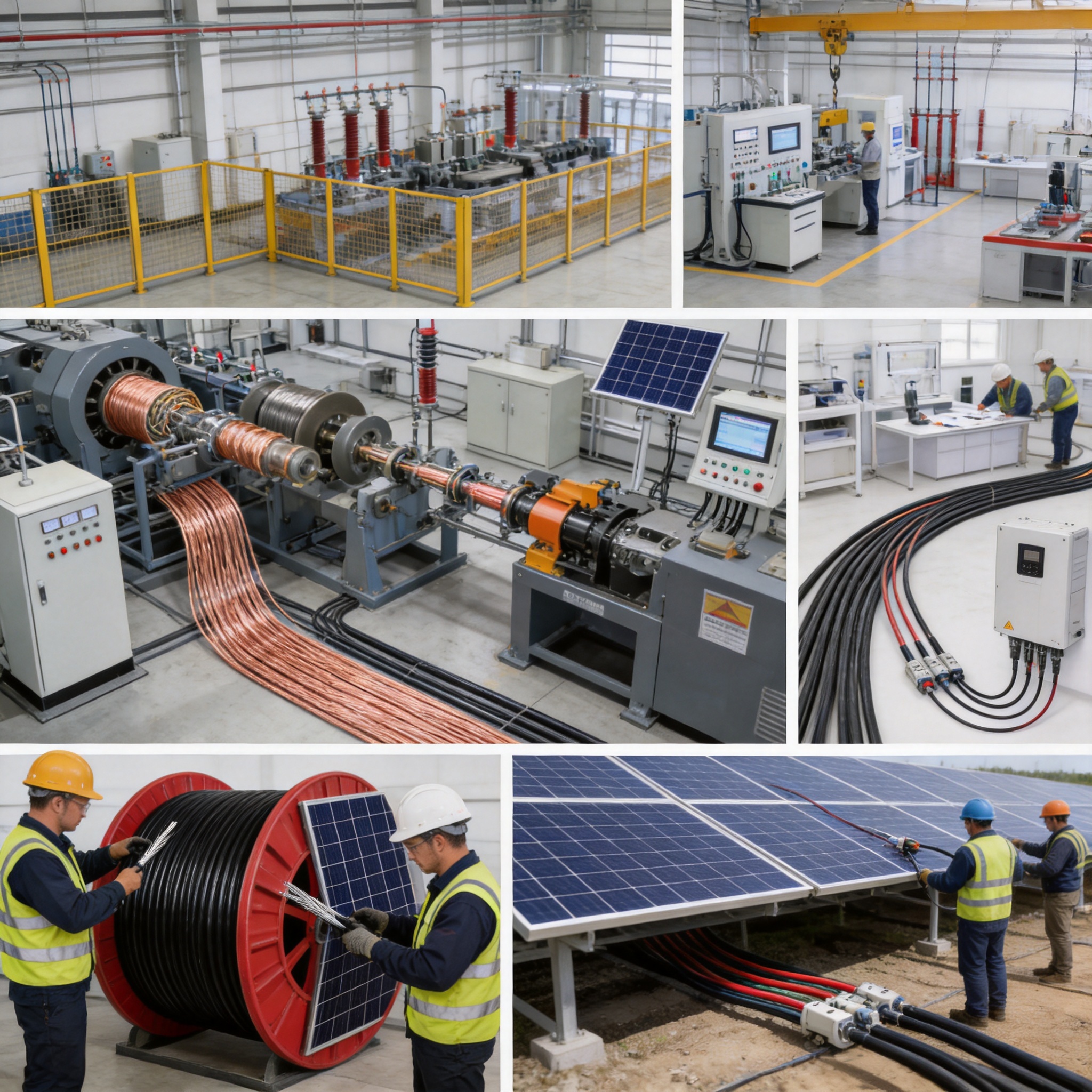
The company uses equipment such as online eccentricity monitoring systems, high-voltage series resonance testers, and partial discharge detectors. Online eccentricity monitoring helps identify whether insulation and sheath layers are uniformly distributed around the conductor during extrusion. Consistent concentricity is important because uneven insulation can reduce electrical margins and create localized mechanical weakness.
High-voltage series resonance testing is used for high-voltage electrical performance evaluation. Partial discharge detection can identify localized electrical activity associated with defects, voids, contamination, or weak points in insulation systems. These technologies support more comprehensive quality control than visual inspection alone.
The company maintains certifications and management systems including ISO 9001 quality management, ISO 14001 environmental management, ISO 45001 occupational health and safety management, and ISO 50001 energy management. It also reports certifications or management systems related to intellectual property, green management, social responsibility, and after-sales service.
Environmental and quality considerations are particularly relevant to photovoltaic cables because the product is used in renewable-energy infrastructure. The use of LSZH XLPO materials and compliance with RoHS environmental directives support a more environmentally responsible product approach. Manufacturing energy management and process control can further improve resource efficiency and production consistency.
Advantages Compared with General-Purpose Cable Options
The first advantage of dedicated photovoltaic cable is environmental durability. General-purpose electrical cables may be designed for indoor panels, conduits, buildings, or protected industrial spaces. Photovoltaic cables are specifically developed for continuous outdoor exposure to UV radiation, ozone, moisture, temperature cycling, and mechanical movement.
The second advantage is conductor corrosion protection. Tinned copper is better suited to humid and corrosive environments than untreated copper. This can help stabilize connection quality and reduce the risk of increased resistance caused by oxidation.
The third advantage is thermal capability. Solar arrays can produce elevated cable temperatures, particularly in high-irradiance locations and beneath tightly packed modules. Cross-linked polyolefin insulation and sheath materials provide improved resistance to heat and deformation compared with many ordinary cable materials.
The fourth advantage is system flexibility. A single-core photovoltaic cable with suitable bending performance is easier to route around modules and supporting structures. The minimum bending radius of not less than four times the outer diameter supports practical installation when the cable is handled correctly.
The fifth advantage is fire-related material performance. LSZH materials reduce smoke and avoid halogen gas emissions during combustion. This may be especially valuable in rooftop, commercial, industrial, transport, and enclosed applications where people and sensitive equipment are nearby.
The sixth advantage is long-term lifecycle alignment. A photovoltaic plant may be financed and operated over a period of 25 years or longer. A cable designed for a comparable service life is better aligned with the economic objectives of the project than a product intended for short-term or protected applications.
These advantages should be evaluated together. No single feature determines cable quality. The best product is one that combines appropriate standards, stable materials, accurate production, verified electrical performance, reliable environmental resistance, and technical support for project implementation.
Applications in Different Solar Environments
Utility-Scale Solar Farms
Large ground-mounted solar farms require extensive DC cable networks. PV cable may be installed between modules, along mounting structures, in cable trays, across equipment rows, and between combiner boxes and inverters. The cable must withstand sunlight, wind, dust, temperature variations, and possible ground contact while remaining easy to identify and maintain.
For long runs, engineers must carefully evaluate voltage drop and current capacity. Larger H1Z2Z2-K cross-sectional areas can support higher-current DC trunk circuits, subject to system design and standard requirements. Cable routing should minimize unnecessary length, avoid sharp edges, and provide adequate support against wind-induced movement.
Rooftop Photovoltaic Systems
Rooftop systems often have limited ventilation and elevated surface temperatures. Cable routing may pass beneath modules where heat can accumulate. UV exposure is also significant because the cables are frequently located in open areas rather than enclosed conduits.
Flexible photovoltaic cable simplifies routing around roof penetrations, module frames, rail systems, and inverters. Proper clips and cable management devices should be used to prevent cables from resting on sharp roof materials or hanging in loops that can collect water.
Desert and High-Temperature Projects
Desert installations combine high solar radiation, large daily temperature changes, dust, dry air, and occasional severe weather. Cable materials must resist heat and ultraviolet exposure while retaining flexibility. Current derating becomes particularly important when ambient temperature approaches the upper design range.
Dust can accumulate on module surfaces and supporting structures, while sand movement may cause abrasion. Cable routing should prevent unnecessary contact with abrasive surfaces. Regular inspection can identify sheath damage before it becomes an electrical problem.
Coastal and High-Humidity Projects
Coastal solar plants may be exposed to salt spray and high humidity. These conditions increase the corrosion risk for metallic components and connections. Tinned copper conductors, resistant insulation materials, sealed connectors, and appropriate installation practices provide a more robust solution than ordinary untreated conductors.
High-Altitude Installations
At high altitude, solar radiation can be intense while temperatures may change rapidly. Equipment may also face lower atmospheric pressure and difficult access for maintenance. Cable selection should follow the project’s insulation coordination and environmental requirements, while mechanical routing should account for wind and temperature movement.
Installation and Maintenance Considerations
Before installation, cable drums and coils should be inspected for transport damage, moisture ingress, or deformation. Cable ends should remain sealed until the product is ready for use. Storage should protect the cable from prolonged exposure to direct sunlight, standing water, contamination, and excessive mechanical loading.
During unwinding, the cable should be pulled from the drum in the intended direction without creating kinks. Excessive pulling force can damage the conductor or insulation. The cable should not be dragged over rough ground or sharp edges, and temporary supports should be used when long lengths are being positioned.
Connection work is a critical part of photovoltaic cable installation. Connectors must be compatible with the cable cross-sectional area, conductor construction, voltage rating, and environmental conditions. Crimping tools should be suitable for the specified connector system and correctly adjusted. An incomplete or excessive crimp may create high resistance and localized heating.
Positive and negative conductors should be routed and identified according to the project design. Cables should be supported so that they do not rest on module edges, roof surfaces, or structural components capable of causing abrasion. Connections should not be placed in areas where water can accumulate.
Maintenance inspections may include visual examination of sheath condition, connector integrity, cable support, signs of overheating, discoloration, corrosion, abrasion, animal damage, and excessive movement. Thermal imaging can help identify abnormal resistance or overloaded connections. Insulation resistance testing and other diagnostic procedures should be performed by qualified personnel using methods suitable for the system voltage and equipment.
Selection Guide for Project Engineers
Project engineers should begin by identifying the required standard. If a project specification calls for 2PfG 1169/08.2007, PV1-F may be appropriate within its available size and voltage range. If EN 50618:2014 is required, H1Z2Z2-K should be evaluated within the applicable system design.
The next step is to determine system voltage and maximum current. The cable must have a voltage rating higher than the maximum system voltage and a current capacity that remains adequate after all applicable correction factors. Designers should calculate voltage drop for long circuits and determine whether a larger cross-sectional area is economically justified.
Installation conditions should then be reviewed. The same cable size may have different permissible currents in free air, on a surface, in a conduit, in a tray, in a trench, or in a grouped arrangement. Ambient temperature, direct sunlight, thermal insulation, soil conditions, and the number of adjacent loaded circuits should be included in the calculation.
Environmental factors should also be documented. The project team should identify UV exposure, humidity, salt spray, chemical contamination, dust, temperature extremes, mechanical impact, rodent activity, and possible water immersion. This information helps confirm whether the cable’s material system and construction are suitable.
Finally, procurement teams should verify documentation, test reports, cable markings, packing, quality certificates, and technical support arrangements. Traceability is useful for large projects because cable batches may be delivered over an extended construction period. Clear documentation supports inspection, commissioning, and future maintenance.
Quality Assurance from Raw Material to Finished Cable
Reliable photovoltaic cable production begins with controlled raw materials. Copper purity, tin coating quality, polymer formulation, colorants, additives, and packaging materials should be managed according to defined specifications. Material identification and incoming inspection help prevent unsuitable materials from entering production.
During conductor stranding and tinning, process parameters affect flexibility, resistance, surface condition, and dimensional consistency. Uniform tin coverage helps protect the copper strands and supports reliable termination. Conductor resistance testing verifies that the finished conductor meets the required electrical characteristics.
During insulation and sheath extrusion, temperature, pressure, line speed, cooling, and cross-linking conditions must be controlled. Online eccentricity monitoring can identify deviations while production is in progress, allowing timely adjustment. Dimensional checks verify conductor diameter, insulation thickness, sheath thickness, and finished cable diameter.
Finished cable testing may include conductor resistance, voltage withstand, insulation resistance, dimensional inspection, tensile and elongation testing, heat aging, low-temperature bending, environmental resistance, and other tests required by the applicable standard. Sampling plans and routine testing should be supported by documented quality procedures.
Production traceability links test results and material records to the finished cable. This is important for major solar projects where the cable may be installed across large sites and delivered in multiple batches. A structured quality system gives customers greater confidence that the delivered cable matches the approved technical specification.
Environmental Responsibility and Safety
Photovoltaic cable supports the expansion of renewable-energy generation, but responsible manufacturing remains important. The use of LSZH XLPO materials reduces halogen-related environmental and safety concerns during combustion. RoHS compliance further supports restrictions on certain hazardous substances.
The manufacturer’s reported ISO 14001 environmental management and ISO 50001 energy management systems reflect an organized approach to environmental performance and energy use. These systems can support continuous improvement in material efficiency, production energy consumption, waste management, and process monitoring.
Occupational safety is also important in cable manufacturing. Cable production involves high temperatures, rotating machinery, electrical testing, heavy drums, and specialized chemical or polymer materials. An ISO 45001 occupational health and safety system supports structured risk management and safer operating practices.
For customers, responsible manufacturing can contribute to project sustainability reporting. Solar developers increasingly consider not only the operating emissions of a renewable-energy asset but also the materials, production processes, supply chain, and end-of-life management of its components.
Frequently Asked Questions
What is photovoltaic cable used for?
Photovoltaic cable is used for DC power transmission between solar modules, module strings, combiner boxes, DC distribution equipment, and inverters. It is designed for outdoor photovoltaic environments and is not simply a replacement for ordinary building wire.
What is the difference between PV1-F and H1Z2Z2-K?
PV1-F and H1Z2Z2-K are photovoltaic cable types associated with different standards and production ranges. PV1-F is listed with 2PfG 1169/08.2007 and is available from 1.5 to 35 mm² in the described range. H1Z2Z2-K is listed with EN 50618:2014 and is available from 1.5 to 240 mm², making it suitable for a broader range of current-carrying applications.
Why is tinned copper used in solar cable?
Tinned copper helps protect copper strands from oxidation and corrosion in humid and outdoor environments. It also supports soldering and contributes to stable electrical connection performance.
Can photovoltaic cable be installed outdoors?
Yes. Photovoltaic cable is specifically designed for outdoor use and offers resistance to UV radiation, ozone, moisture, temperature variation, and other environmental stresses. Correct support, routing, connector assembly, and protection remain necessary.
What does LSZH mean?
LSZH means low-smoke zero-halogen. LSZH materials are designed to produce limited smoke and avoid the release of toxic halogen gases during combustion compared with conventional halogen-containing materials.
What is the expected service life of the cable?
The product is designed for an expected service life of not less than 25 years under suitable operating, installation, and environmental conditions. Actual service life depends on temperature, mechanical stress, chemical exposure, installation quality, and maintenance.
How should cable size be selected?
Cable size should be selected according to system voltage, maximum current, installation method, ambient temperature, grouping, voltage drop, short-circuit requirements, and applicable standards. The reference current tables must be adjusted using the correct environmental and installation factors.
Can the cable be used in coastal areas?
The cable’s tinned copper conductor and resistant polymer materials support use in coastal environments. However, the complete system must also use suitable connectors, glands, supports, and protective components designed for salt-laden air and humidity.
Why is the bending radius important?
Maintaining the specified bending radius prevents excessive stress on the conductor, insulation, and sheath. The stated minimum bending radius is not less than four times the cable’s outer diameter, subject to the applicable handling and installation conditions.
What testing capability does the manufacturer have?
The manufacturer operates production and testing lines and uses equipment including online eccentricity monitoring systems, high-voltage series resonance testers, and partial discharge detectors. These systems support dimensional, electrical, and insulation quality control.
Conclusion
Photovoltaic cable is a critical component of safe, efficient, and durable solar power infrastructure. Its performance affects the continuity of DC power transmission, the reliability of electrical connections, maintenance requirements, and the long-term return on investment of a photovoltaic project.
The PV1-F and H1Z2Z2-K products described here combine tinned copper conductors, cross-linked LSZH XLPO insulation and sheath materials, wide temperature capability, UV and ozone resistance, strong flexibility, and long-term outdoor durability. Their stated standards and size ranges support use in module interconnections, string circuits, combiner-box connections, and larger DC collection systems.
Compared with general-purpose cable, dedicated photovoltaic cable provides better alignment with the environmental, thermal, mechanical, and electrical requirements of solar installations. Its advantages are most valuable when supported by correct sizing, careful installation, suitable connectors, and regular inspection.
Wuxi Guanghuan Cable Co., Ltd. strengthens this product offering through a long operating history, a broad cable manufacturing portfolio, advanced production and testing equipment, technical personnel, and certified management systems. Its manufacturing capabilities support consistent production and provide customers with a more complete supply solution for photovoltaic and other energy applications.
As solar generation continues to expand into utility-scale, commercial, residential, desert, coastal, and high-altitude environments, cable quality will remain an essential part of project reliability. Selecting a photovoltaic cable engineered for long-term outdoor service is a practical investment in energy availability, electrical safety, and lifecycle performance.
References
1. EN 50618:2014, Electric Cables for Photovoltaic Systems with a Voltage Rating of 1.5 kV DC.
2. 2PfG 1169/08.2007, Requirements for Photovoltaic Cables.
3. International Electrotechnical Commission, photovoltaic system design and installation principles.
4. International Electrotechnical Commission, cable current-carrying capacity and thermal rating principles.
5. RoHS Environmental Requirements for the Restriction of Hazardous Substances in Electrical and Electronic Equipment.
6. ISO 9001, Quality Management Systems.
7. ISO 14001, Environmental Management Systems.
8. ISO 45001, Occupational Health and Safety Management Systems.
9. ISO 50001, Energy Management Systems.
10. Manufacturer technical data for PV1-F and H1Z2Z2-K photovoltaic cables, including construction, ratings, current-carrying capacity, and temperature correction factors.
Product: Photovoltaic Cable (PV Cable)


Copyright © Wuxi Guanghuan Cable Co., Ltd. All Rights Reserved. Power Cables Manufacturer Electrical Wire And Cable Factory

